
Introduction
Follow along with these simple build videos and have your RepBox up and running in no time!
Parts
No parts specified.
-
-
Before you get started please be sure you've read and completed the pre-build guide which will go over all the parts that you should have and tools you'll need.
-
-
-
The first thing you'll want to do is decide how you want the exit panels configured: With the holes facing towards the front or back or one of each direction
-
Your RepBox includes enough plugs to fill all the exit holes you decide not to use.
-
In the pictured configuration we've set the top panel to have them face front. But the panel can rotate 180 degrees and is interchangeable with the base panel.
-
Mosaic Pallette 2 Top Direct feed mode pictured. (Secondary Exit Panel Holes Top Front)
-
You may also want to consider this setup if you want to feed your wall mounted Mosaic Palette 2 from above: https://www.thingiverse.com/thing:345831...
-
-
-
For this step you'll need:
-
Part 4: Top/Bottom Exit Panel
-
Part C: 13PCS- Exit Plugs
-
Press in the exit plugs as shown before you start base assembly. It's much easier to do while the panel is laying flat on the table. Fit should be snug.
-
TIP: If you have a deburring tool, adding a slight chamfer to the holes makes it easier to press the plugs in.
-
GENTLE tapping with a small hammer may make this easier on the MDF version. This is not recommended on the acrylic version as you risk cracking it if you strike the wrong spot.
-
-
-
For this step you'll need:
-
Top/Bottom Panel Part 4 from last step with plugs installed.
-
2PCS- Part 2 Outer Track guides
-
6PCS- Part 19 3D Printed Brackets
-
3D Printed Exit Clip (Replaces old Part 30 Styrene Strip)
-
6PCS- TF Screw Fasteners
-
Line up the outer track guides on the top/bottom panel as shown on the video. Decide whether you want the bottom exit holes to be at the front or back of the box (closest to the wall is most common)
-
Lay out the brackets as shown in the video one at each corner and one in the center. You will attach the brackets in the next step.
-
-
-
NOTE: Version 2.25 now uses a 3D Printed Exit Clip to replace the older style Part 30 Clamp Strip in v2.2. Better visuals of this new part can be seen in step 14 below.
-
Line up the base panel as shown with the exit plug holes lined up on the side you prefer. In this video we've chosen to have our exit holes at the rear of the box.
-
Move the panels to the edge of a table so you can easily run a TF Screw through the corners and center holes while holding the bracket beneath.
-
Orient the brackets so the side with the singular hole on the flat edge is facing up. When the bracket is fastened it should be flush with the edge of the panels
-
Start with the front center hole and run the TF screw through the front 3D printed exit panel clip (v2.25) or clamp strip ( v2.2 part 30) before going through the outer track guide and base panel and ultimately threading into the bracket beneath.
-
Repeat this for all the corners and the rear center. The Exit Clip (v2.25) or clamp strip ( v2.2 part 30) will only be on the side you have chosen to orient to the front.
-
-
-
This is what your base assembly should look like with the brackets screwed on.
-
The corners should be left a little loose now so we can get the sidepanels snugged up later on.
-
-
-
Verify once more that the base exit holes are where you want them. Again exit panel clamp strip should be located at the front center hole. In our configuration here the exit holes are at the rear of the box (closest to the wall if wall mounted)
-
The Rear Panel (Part 1) is oriented so the small rectangular holes are located at the bottom of the box and the double hole sets are at the top.
-
Tip the base assembly on its side and orient the back panel as shown in the video here. The finished/painted side (if MDF version) should be facing the inside of the box.
-
Attach the rear panel to the base assembly using 3 TF Screws at the corners and bottom center of the panel as shown.
-
Leave the corner connections slightly loose for now. We'll tighten them at a later step when we're ready to get the sidepanels aligned.
-
-
-
The plinth is what gives strength and rigidity to the base of the box. To complete this step you will need:
-
1PC- Part 11: Stringer Support Bar
-
2PCS- Part 12: Base Stringers
-
1PC- Part 13: Base Faceplate
-
Start by orienting the base/back panel assembly on its back as shown. Fit the Base stringers into the rectangular notches beneath the box as shown.
-
Add the Stringer Support Bar (Part 11) to the front edge of the base panel as shown. Fit the stringer tabs into the rectangular notches in the panel as shown. DO NOT FASTEN IT TO THE BRACKETS YET
-
Cover the stringer support bar with the Base Faceplate (Part 13) as shown. The bottom edges of it and the Stringer support bar should line up. Fasten to the front 3 brackets with three TF screws as shown.
-
Lay the assembly back down onto the base. You'll notice you've created a small channel for the exit panel to rest in. If you're considering adding silicone to your box joints this would be a good time to lay a bead in place.
-
-
-
Starting with v2.25, MDF RepBoxes now has an Outer and Inner Sidepanel for each side. Your outer panel will vary depending on the version you ordered. The default panels include our back to back Repkord "R" cutouts but custom / branded versions may include a printed styrene panel.
-
The inner panels will always be the ones with the slots cut into them for the top, back, base, and exit panels to nest into. Outer panels simply lay atop the inners and use the same set of screw holes to fasten to the brackets. We will update photos as we are able.
-
Lay out your side panel bundle with the "R" facing outwards. Tip the assembly on its side so you can fasten.
-
If you ordered custom sidepanels you would layer them over the standard sidepanels at this point and fasten through the same set of holes as the standard sides.
-
-
-
Newer panel sets may or may not have the Repkord "R" branding on the side. This is completely normal and does not affect the performance of your box.
-
As mentioned in the previous step. If you have CUSTOM SIDEPANELS you would simply layer them on top of the standard sidepanel at this point and fasten through the common set of holes.
-
Using two TF screws only fasten the bottom corners of the side panels for the time being.
-
Hold the other sidepanel in place as you rotate to fasten the bottom panel, again with only the bottom corner fasteners for now.
-
Only fasten one side about half way for now so you can fit the track guide and front exit panels in the next step.
-
-
-
With one of the side panels still loose slide it away from the box assembly and slip in Part 3: Center Track Guide.
-
Don't tighten the side panels just yet. We're going to add the front exit panel in the next step using the same method.
-
-
-
For this step you'll need the following:
-
1PC- Part 9: Exterior Exit Panel
-
1PC- Part 10: Interior Exit Panel
-
2PC-3D Printed Flange Nuts (Part 31) & 2PC- TF Screws
-
Laser cut "Drumstick Tool" included with the faceplate panel set.
-
Sandwich the Interior and Exit panels together as shown so that the finished side (MDF version only) is facing outward on both sides. The interior panel will be taller than the exterior. This is normal. When the screw holes are lined up the top edge of both panels should be flush as shown.
-
Press two TF screws through the holes in both exit panels as shown. Fasten the flange nuts with the flange side towards the interior exit panel as shown. Hold the flange nuts in place with the included "Drumstick tool" and tighten the screws. Repeat the process for both sides.
-
Fit the assembly into the rectangular notches of the sidepanels as shown. Press the two sidepanels tightly against the base/back assembly. You may now tighten the bottom two TF screws on the side you left loose so it all stays together.
-
-
-
NOTE: We have now added a much better 3D printable Exit clamp. We are starting to integrate them into our latest printed parts sets but if you'd like to print your own you may do so by downloading it from our part file repository here. See the following step for recent images of it installed.
-
Rotate the Exit Panel Clamp strip (Part 30 from the styrene roller sheet S) so that its laying on top of the front exit panel assembly as shown. You may need to loosen the screw holding it in place to get it on top of the assembly.
-
Tighten the screw holding the clamp strip so it starts to bend and forms to the angle between the exit and base panels. This bend is normal and is what holds the exit panel in place from inadvertently being pressed into the box when attaching the exit fittings.
-
-
-
This is a look at the new 3D printable exit clip available in the Optional Enhancements section of our Part Repository Here
-
Pictured with and without the latch plate from the optional seal kit.
-
-
-
RepBoxes produced between late March and Mid-April 2021 may have come with a longer exit clamp strip on Sheet S. It is installed as follows but has since been replaced with our new printable Exit Clip stored in our public file repository here. We recommend printing one to replace the old strip design.
-
-
-
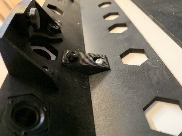
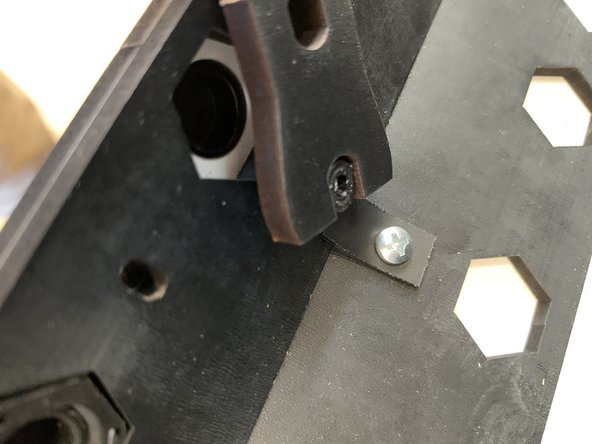
Time to add the brackets to the top of the back panel.
-
It may seem counterintuitive but the bracket will line up to create a "hook" should you decide to wall mount your box. This is correct and normal.
-
Starting with the center use two TF screws fasten the bracket to the back panel using the two holes on the one short edge of the bracket as shown.
-
-
-
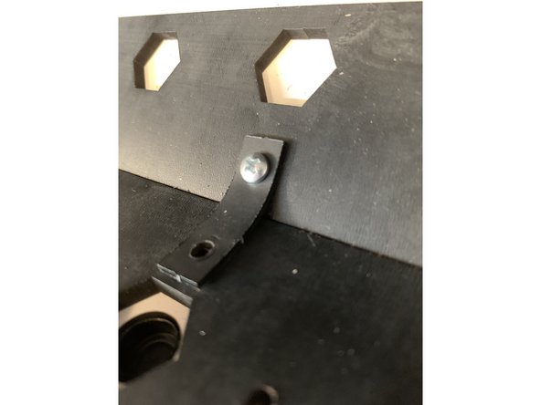
For the top rear corners you will only be using one fastener on the side of the bracket furthest away from the sidepanel to secure it to the back panel as shown.
-
-
-
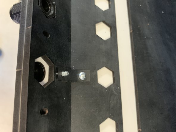
Connect the top rear brackets to the sidepanels as shown.
-
Leave one side only partially tightened so we can slip the top/lid panel assembly in more easily in later steps.
-
-
-
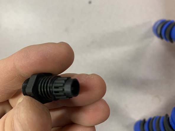
Due to slight variances from suppliers your exit fittings may look slightly different from those pictured. This is perfectly normal and they will still function the same.
-
The fittings you receive may or may not have rubber washers installed when you receive them. These washers are not necessary for the functioning of the RepBox and WILL LIKELY INTERFERE WITH ALLOWING YOU TO THREAD THE FITTING INTO THE NUT UPON INSTALLATION
-
In the event that your exit fittings do not grip the nut in the next step verify that you have removed the rubber washer and then flip the nut over in the hexagonal nut trap of the exit panel and try again.
-
Pic 2 and 3 show the internal compression mechanism of the exit fitting with its cap removed. You'll notice a series of small "teeth" that should have a tall rubber gasket installed between them as shown in Pic 2. As the cap is tightened it compresses this gasket around any optional PTFE tubing you may have installed.
-
You may need to twist the cap completely to get a firm grip on any optional PTFE tubing you may be using. If its not gripping make sure the gasket is indeed installed and you may always add pieces of tape to the outside of the PTFE tube to increase compression/grip.
-
-
-
This is a good opportunity to attach the exit fittings and plugs in the configuration you'd like while there's no lid in the way.
-
We've chosen a default setup to allow maximum room for six 1kg spools in this configuration. You may decide to orient differently depending on the width of the spools you're using.
-
Press plugs into the unused holes as shown.
-
Extra fittings and roller sets are available at www.repkord.com/repbox if needed.
-
-
-
If you've ordered the optional seal kit for your RepBox this is a good opportunity to install it while the lid isn't in the way.
-
With two TF screws attach 3D Printed part 21 from your optional seal kit as shown.
-
The holes on the front exit panels are slotted to allow for fine adjustment of the lid fastening in later steps. This is normal. For now set it at the lowest (furthest into the box) setting.
-
-
-
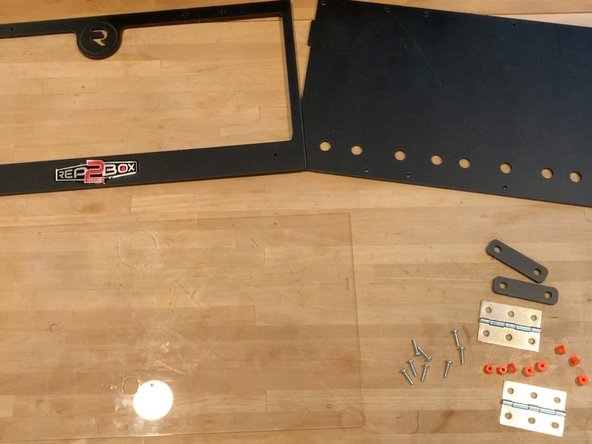
For the following Top/Lid assembly you will need the following parts:
-
1PC- Part 15: Front Face Plate
-
1PC- Part 4: Top/Bottom Exit Panel
-
1PC- Part 16: Acrylic lid
-
1PC- Part 28: Set of 2 Hinges
-
2PCS- Part 17: Faceplate Clamps
-
10PCS- 3D Printed Flange Nuts
-
8PCS- TF Screws
-
-
-
Remove any protective films from the acrylic lid as shown.
-
IMPORTANT: If you have purchased the humidity hunter kit upgrade, now is a good time to knock out the acrylic disc on your lid. It is affixed by sacrificial tabs. IF YOU DID NOT RECEIVE THIS KIT LEAVE THE DISC IN PLACE AND PROCEED TO THE NEXT STEP
-
Start by scoring the tabs that hold the knockout to the lid with pair of side/flush cutters or a hobby knife on BOTH SIDES of the acrylic lid. Gently wiggle the disc back and forth until the tabs give way and the disc pops out. Be patient and work slowly so as not to crack the lid.
-
Repeat this process for the lid faceplate (Part 15) and remove the disc with the recessed "R" in it using the same technique.
-
-
-
Before we start assembly press the exit plugs into the top panel the same way we did for the base. Much easier to do while its laying flat on a table.
-
TIP: If you have a deburring tool, adding a slight chamfer to the holes makes it easier to press the plugs in.
-
You can much more easily remove the plugs in the future to add exit fittings.
-
-
-
Time to press the flange nuts into all the clamping parts we'll need:
-
1PC- Part 5: Top Panel Hinge Clamp
-
2PCS- Part 17: Faceplate Clamps
-
1PC- Part 14: Lid Brace
-
''Lay the following on the table with the finished side (MDF version only) face UP''
-
Press 3D Printed Flange Nuts into the above parts as shown here.
-
-
-
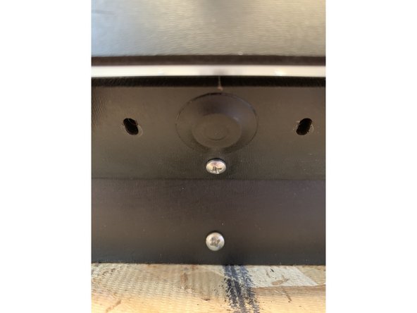
On newer kits your faceplate may not have the dome label installed yet. If not it will be included in your parts tube and should be applied in the dashed outline area at the base of the faceplate now.
-
Use the edge of a table once again to ease along this assembly.
-
Start by lining up your acrylic lid and faceplate so the fastening holes all line up.
-
Unpack your hinges if you have not already done so. You may discard the wood screws if your hinges had some included with the pre-sealed hinge set. These are not needed for this assembly. Find something else creative to do with them and then share. ;)
-
Notice that each hinge has different folding around the hinge pin set. One side will have two folds around the hingepin and the other three. It does not really matter which side is closer to the lid or top panel but laying out both sides to be consistent (both double folds on one side) will make final lid alignment a bit smoother later on.
-
Grab the faceplate clamps (part 17) that you prepared earlier and line them up beneath the lid assembly as shown. Run two TF screws through the hinge, then lid and faceplate, and fasten into the clamp you're supporting underneath. Repeat this process for both hinges on each side.
-
Leave the hinges slightly loose for the time being. You'll do final alignment at a later time.
-
-
-
Retrieve the top panel (part 4) that you plugged up earlier. Decide whether the exit holes will be positioned at the front or rear of the box. In this example we're lining them up to the front so we can set our Mosaic Palette 2 on top of the RepBox for easy feeding.
-
Grab two TF Screws and press them up through the front corners of your top panel as shown. Use two of the round washers found on styrene punch sheet "S" and place those atop the screw sticking through the panel as shown.
-
Place Part 5: Top Panel Hinge Clamp atop the two protruding screws as shown and fasten it down with two of the 3D Printed brackets as shown. The screws will be threading into the long edge of the bracket with the singular hole such that the short edged double hole side is facing forward (toward the outside of the box)
-
Leave the screws slightly loose for now. Will tighten later when we're doing final sidepanel alignment
-
It is normal for there to be play between the hinges and their fastening screws. This is what allows us to do slight adjustments to the lid to optimize fit and seals.
-
-
-
The washers from the last step are there to allow us to slip the hinges between the top panel and the clamp bar as shown here.
-
Lay the top panel on the edge of the table with the hinge side facing you as shown.
-
Carefully slip each of the hinges between the top panel and lid clamp.
-
Use the top seal bar (part 26) that you prepared with the flange nuts in earlier steps to fasten the top hinges to the top panel. Align the seal bar so that the small tabs fit in behind the brackets towards the inside of the box.
-
Four TF screws will pass through the top lid, then the hinges, top clamp, and finally the top seal bar into the set flange nuts as shown.
-
Leave the screws slightly loose so the hinges can wiggle around a bit. We will tighten them in a later step when we do final alignment
-
It is normal for there to be play between the hinges and their fastening screws. This is what allows us to do slight adjustments to the lid to optimize fit and seals.
-
-
-
Critical step for optimal sealing. Read / watch carefully.
-
The purpose of the lid "bowing" is to hold the bottom corners of the lid more tightly against the sealing gasket for those who have chosen to add the optional seal kit to their configuration.
-
Tip the top / lid assembly on its side and grab the lid brace (Part 14) that you prepped with the 3D Printed Flange nuts from the earlier step.
-
The lid brace should be flipped so that the finished side (MDF version) and 3D Printed nut flanges are facing the inside of the box.
-
Fasten one side of the lid brace loosely with a TF Screw. As is, with the brace laying on the lid the holes WILL NOT line up. This is what allows us to create the bow effect. The lid brace will be acting like the string of a bow holding the whole thing in tension.
-
Flip the lid assembly over and carefully flex the lid and faceplate assembly as shown so that you can press a TF screw in on the unfastened side of the panel and start to thread into the flange nut. This takes a little bit of finesse so be patient. It helps if you keep the screws loose to start to maximize the amount of lid flex.
-
-
-
For the standard handle set (no seal kit) simply affix the 3D printed handle set (Part 20) to the acrylic lid with two TF screws as shown here.
-
Tip the lid / top panel assembly on edge and run two TF screws through from the inside of the box outward tapping directly into the 3D Printed Handle set.
-
-
-
If you ordered the Optional Seal Kit. Prepare your 3D printed Handle Set as follows.
-
The handle set for the seal and non-seal kit versions of the box are the same. The latter just requires you to free the top portion of the handle from the base to operate the latch mechanism.
-
Start by removing the mouse ears from the corners of the bracket (sacrificial to help with the 3D printing bed adhesion)
-
-
-
Using flush cutters or a hobby knife clip the ten small attachment strips at the base of the print.
-
Remove the top of the handle from the base and clean up any remaining attachment strips.
-
-
-
Remove any remaining attachment strips from the top handle.
-
Should you ever need to reattach the top handle to the bottom you can easily do so with two TF screws located in the inner holes of the handle set.
-
-
-
This video was actually pulled from a v2.1 box and will be updated shortly. The process however is the same.
-
If you purchased the optional seal kit it will have included a keyed latch kit as seen here. Start by pressing the lock core through the acrylic lid from the outside in as shown.
-
If the metal latch bar or core nut is attached you'll need to remove it first.
-
Place a single key into the latch core as shown
-
Fasten the lock core to the lid using the hex nut included. The "drumstick" tool can be used to tighten the included nut. Keep in mind that this nut is really only to hold the lock core in place and not a lot of torque is required. The 3D Printed handle set will ultimately lay over top of the outside of the lock core and keep it in place too.
-
To use the "Drumstick" tool you will need to pull the lid brace away from the acrylic lid so you can temporarily tighten the nut.
-
With the key in the vertical position attach the metal latch bar to the latch core with the provided screw and a phillips head screwdriver. Make sure the cutout in the latch bar is facing you and aligned as shown in the video.
-
Verify the operation of the latch with the key in it and then return it to the open position.
-
-
-
Time to merge the base/sidepanel assembly with your newly built top/lid assembly!
-
For illustration purposes we first show the mount reinforcement bar (part 18) being laid in place where it will ultimately go but we are not fastening it just yet.
-
Lay the top lid into the keyed rectangular holes of the sidepanels and pull the one loose sidepanel away from the assembly to fit the other side of the top panel in. Then press the loose sidepanel in and tighten the top rear corner bracket to hold it in place
-
Rotate the box 180 degrees and slip the mount reinforcement bar (part 18) in the open space between the rear brackets and the top plate.
-
Fasten the top panel to the rear brackets with five TF screws as shown.
-
-
-
Almost there! Add a TF screw to the top front corners of the sidepanel now and fasten.
-
At this point we can go through and tighten all the corner connections as we snug up the side panels to all the interior box joints. The goal is to get those joints as close to each other as possible and minimize any gaps.
-
Slight variances from the laser cutting process may occur. While we try to account for this with our corner adjustments if you are concerned with maximizing the seals of your box joints you may consider running a small bead of silicone at each of the joints to help prevent air incursion.
-
-
-
For this step you'll need:
-
1PC- Part 29: Steel Lid Prop
-
2PCS- Part 6: Washers from styrene sheet "S"
-
1PC- Part 31: 3D Printed Flange Nut & "Drumstick" Tool
-
Pick which side you would like your lid prop to be on and press a TF Screw from outside to inside of the sidepanel that will support it.
-
Add one of the washers to the exposed screw posts as shown
-
Attach the lid prop to the screw post as shown. NOTE: This hole is tight intentionally and you may need to turn the screw to help pull the lid prop on to it. WARNING: Metal can be sharp handle carefully or use gloves so as not to cut yourself.
-
Fasten the whole thing with a flange nut. Orient the nut so that the flange side butts up against the lid prop and hold it in place with the "Drumstick" tool while tightening the screw. NOTE: While the video shows a second washer this is no longer necessary. Only use the one washer between the sidepanel and the prop.
-
-
-
Another angle of the lid prop operation. Note the notch in the acrylic lid to hold the tip of the lid prop in place while the lid is open.
-
-
-
You may have some variance in your lid position as it relates to your lid prop and sidepanels. This is normal. You can compensate for this by adjusting the hinge position.
-
To start turn the RepBox upside down so its laying on the top panel and let the lid open onto your work surface.
-
Slide the whole thing to the edge of the table so you can access the hinge screws
-
Press the lid firmly towards the top panel to move the hinge pins as close as possible to the top panel and lid edges.
-
Slide the lid left or right to allow space for the lid prop on your side of choice.
-
Tighten the hinge screws
-
Repeat adjustment as necessary until you are happy with the alignment of the lid.
-
-
-
Congrats! You've made it through the main assembly. No small feat. Maybe enjoy a life saver or two from your Mini RepSaver box if you haven't eaten them all already ;)
-
When you're ready its time to move on to Stage 3: Roller Assembly ->
-
-


Cancel: I did not complete this guide.
2 other people completed this guide.
