Tools
Parts
No parts specified.
-
-
Take a moment and separate out all the roller side panels (Part 7) from the styrene sheet "S". There should be 19 of them in total.
-
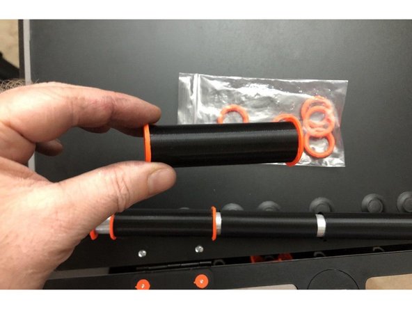
Bear in mind there are other parts on this sheet like the washers (Part 6) and the Exit Panel Clamp Strip (Part 30) Their use is outlined in the Main Assembly guide. These may also be extra parts left over from your build you may wish to hang on to as replacements in the future if needed.
-
-
-
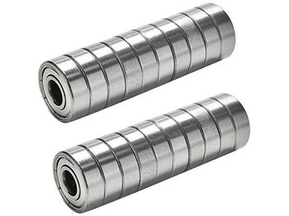
The RepBox uses standard 608 skate bearings for its flange roller style assemblies
-
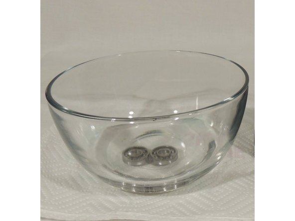
Due to variance in supply, sometimes sets of bearings may come with more excessive grease packing than others. This is completely normal. Given that this is a low speed, weight application this is not necessary and any excess grease should be wiped off or soaked in degreaser / alcohol prior to assembly.
-
Once you've inspected and wiped down or soaked any excess grease from the bearings proceed to the next step.
-
-
-
Using the "Drumstick Tool" secure your 3D printed roller axle part and pre-tap the part by threading a TF screw in and out of each one.
-
This will help alleviate the odds of rounding out the hole in the roller sides by over torquing them.
-
-
-
There are two types of spool rollers for the RepBox: Double Rollers and Single Rollers.
-
The Double Rollers that we're building in this step have a shared side and go in the middle of the box between two spools. There will be enough parts for five of these.
-
The Single Rollers are for the ends of the box and their assembly will be shown in a later step. There will be enough parts for two of these.
-
For Double Roller assembly you will need: 2PCS- 3D Printed Roller Axle- Part 32, 2PCS- 3D Printed Roller Spacers- Part 33, 3PCS- Roller Panels - Part 7, 4PCS - Roller Bearings from parts pack A, 2PCS TF Screws from Parts Pack E
-
Press two of the 3D printed axles into one roller panel as shown. Lay two bearings atop each of the exposed axle posts.
-
Noting the orentation of the assembly you just did, you will now be mirroring this by orienting another roller panel so that the small holes line up with the printed axles when the two are sandwiched together.
-
Place a 3D printed spacer (Part 33) atop each of the exposed thread posts from the TF screws you just set. Place two bearings over each of the spacers and that top it off with one last roller side as shown
-
Screw the two halves of the roller together as shown.
-
-
-
This is what a correctly assembled double roller will look like.
-
You will have enough for five double rollers in your kit.
-
Notice that the bearings are offset to one side of the assembly. This is intentional and allows you to orient your spools closer to the front or back of the box as needed depending on where your filament is exiting the box.
-
-
-
To complete this step you will need:
-
2PCS- 3D Printed Axle (Part 32)
-
2PCS- Roller Panels (Part 7 from Sheet S)
-
2PCS- Roller Bearings from Parts pack A
-
2PCS- TF Screw from Parts Pack E
-
Press two of the 3D Printed Axle Pieces into the styrene as shown.
-
Place two bearings atop the axle posts
-
Align the mating side panel so that the small holes for the screws line up with the 3D printed axles when sandwiched together and fasten with two TF screws as shown
-
-
-
This is what a completed single roller should look like.
-
You will have enough for two single rollers in your kit.
-
The TF screws will pass through the roller axles on the far side. This is normal and will not affect performance.
-
For maximum spacing of spools in the RepBox make your other single roller the mirror image of this so the protruding screw ends are always beneath the spool it is supporting and the screw head can snug closely up against the interior side panel.
-
-
-
Please enjoy this lovely timelapse of assembling the rest of the rollers.
-
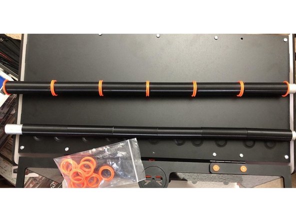
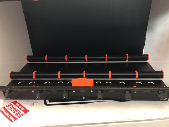
If done correctly, in the end you will have five double rollers and two single rollers.
-
-
-
Notice the orientation of the rollers. You'll want to rotate them so the lead bearing is closest to the side of the spool you're unwinding from to prevent shifting in the box as shown.
-
-
-
That does it for the standard RepBox build! Way to go! If you have any of the optional kits you can find details on how to install them here:
-
-
-
-
-
-
-
If you have version 2.3 the "Parts Pack R" the "RollerSet wiht the Roller Flange from Parts Pack F will replace these steps. Just insert the flange inbetween printed tubes.
-
Cancel: I did not complete this guide.
One other person completed this guide.

