
Difficulty
Moderate
Steps
19
Time Required
- 1 - Main Assembly 19 steps

User-Contributed Guide
This guide is not managed by the site's staff.
Quiz
0
-
-
Before you get started please be sure you've read and completed STAGE 0 HERE which will go over all the parts that you should have and tools you'll need. Then open the assembly video that goes along with this guide. https://youtu.be/nZ5MGGcn6jw
-
-
-
The first thing you'll want to do is decide how you want the exit panels configured: With the holes facing towards the front or back or one of each direction
-
Your RepBox includes enough plugs to fill all the exit holes you decide not to use.
-
In the pictured configuration we've set the top panel to have them face front. But the panel can rotate 180 degrees and is interchangeable with the base panel.
-
Mosaic Pallette 2 Top Direct feed mode pictured. (Secondary Exit Panel Holes Top Front)
-
You may also want to consider this setup if you want to feed your wall mounted Mosaic Palette 2 from above: https://www.thingiverse.com/thing:329632...
-
-
-
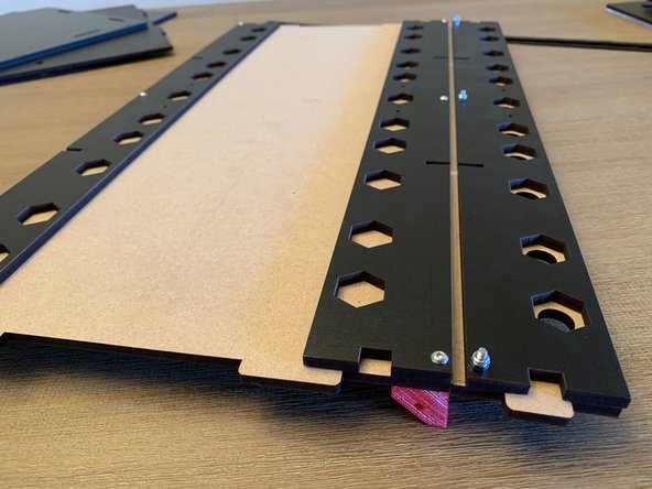
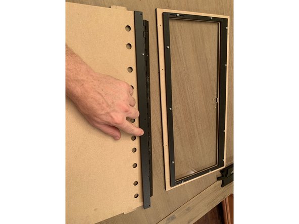
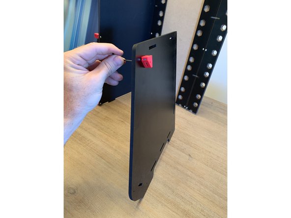
Once you decide which panel to use as your base (with or without exit holes), you're going to start by attaching the vinyl exit panel joint seal to the base panel.
-
Prior to affixing the vinyl. Press out the pre scored holes with a screw or your included allen key.
-
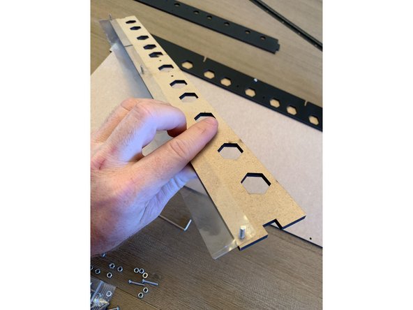
To do this, you'll take one of the rear exit panels (the one with the hexagons) and pressing three 16mm screws through from the finished side and then through the holes in the vinyl as in the first picture.
-
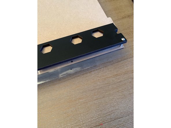
Press the exit panel and vinyl onto the end of the base panel that you've decided will be the front of your box. The vinyl will be sandwiched between the base panel and the exit panel as in the second picture.
-
The hexagons may not appear to line up with anything depending on how you've oriented your secondary exit panel. This is normal and will assist as guides for when you place your rollers later on.
-
-
-
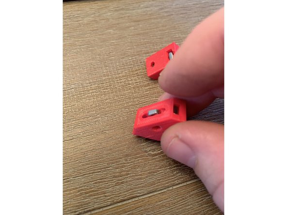
We're now going to set up the mega brackets that hold together the base panel assembly. You will need six (6) brackets for this.
-
Each bracket will need at least 2 square nuts pressed into it. If you press a nut into the wrong hole by mistake simply push your allen key through the opposite side hole of the bracket to press it back out.
-
Start by orienting all 6 brackets as shown in image 1. Press in one square nut on the top corner as shown in pic 1 and one in the corner slot directly beneath it as shown in pic 2. Do this for all six base brackets.
-
The brackets for each of the four corners will need a square nut placed in the horizontal slot along the hypotenuse of the bracket as shown in image 3. Do this to four of the six brackets from the previous step.
-
-
-
The goal is to affix the brackets to the bottom panel of the box as shown in pic 3. Take a look at that first to get a sense of what's happening.
-
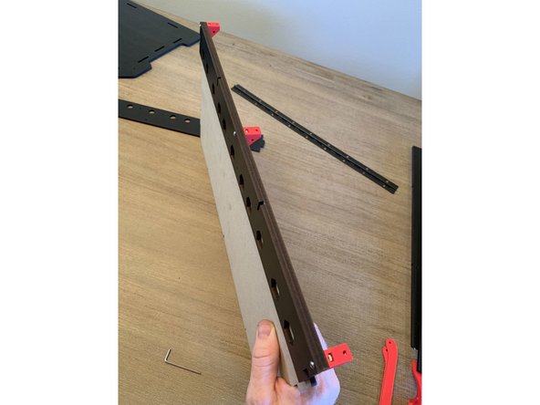
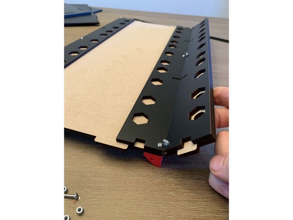
The rear track guide bolts to the rear of the base panel in the same manner as the front but without the vinyl strip sandwiched between as was done with the front side. This is shown in pic 2.
-
With six (6) 16mm screws you will thread through all three panels and tighten into the square nut pressed into the top corner of the bracket as shown in image 3. REMEMBER TO LOCATE THE BRACKETS WITH THE EXTRA SQUARE NUT IN THE CORNERS
-
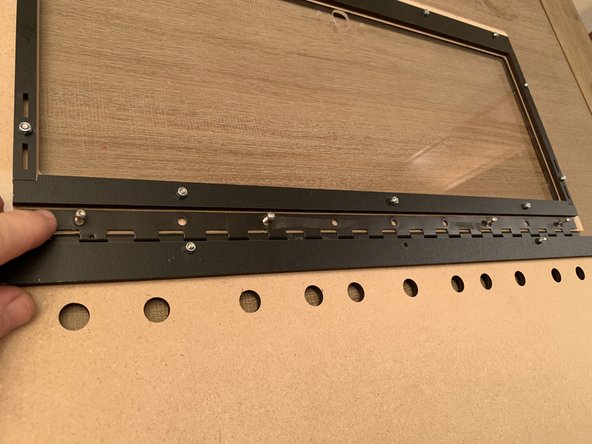
Now take the front exit panel (the one with the circular holes) and sandwich the vinyl between it and the third rear exit panel. You'll notice the hexagons of the rear panel align with the circles from the front centered in them. Run three (3) 16mm screws through the holes at the base and fasten on the other side with the nylon lock nuts.
-
-
-
Pic 1: Exit panel assembly shown from the top with the nylocks holding the front exit panel to the rear with the nylon sandwiched between.
-
When assembled correctly the front exit panel should fold upward and stop at about a 45 degree angle from the base panel.
-
-
-
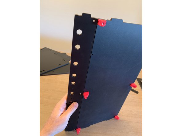
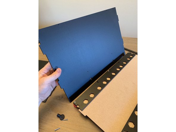
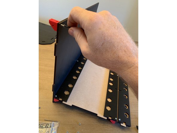
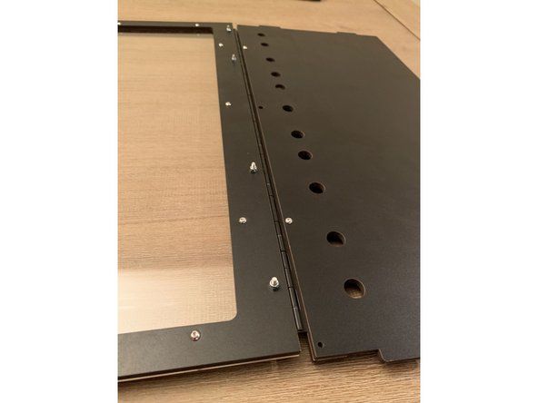
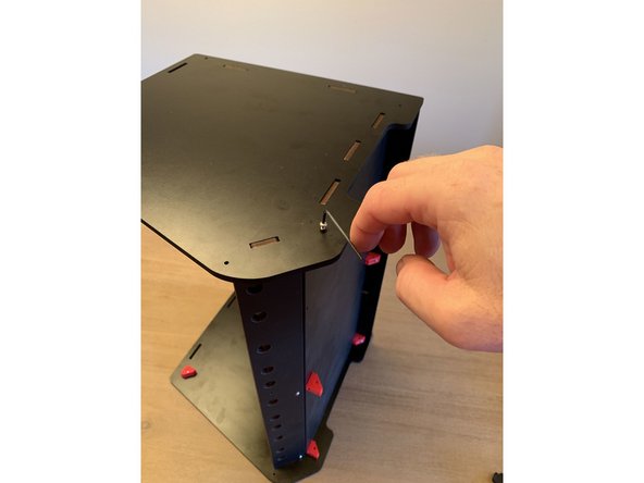
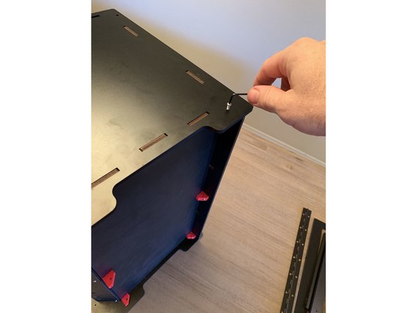
Using three 16mm screws, fasten the rear panel to the base panel with the finished side of the rear panel facing forward as shown in pic 1. The bottom of the rear panel is the side that has the two square notches cut into it.
-
Turn the assembly on end as shown in pic 2 to run the fasteners through to seat in the nuts you pressed into the bottom corner of the brackets earlier.
-
Notice that the bracket does not line up flush with the base of the rear panel. This is intentional.
-
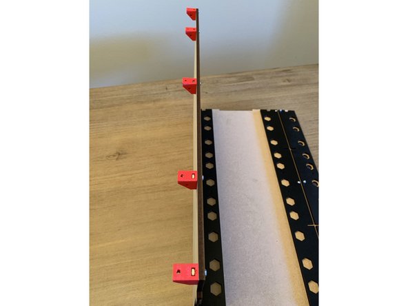
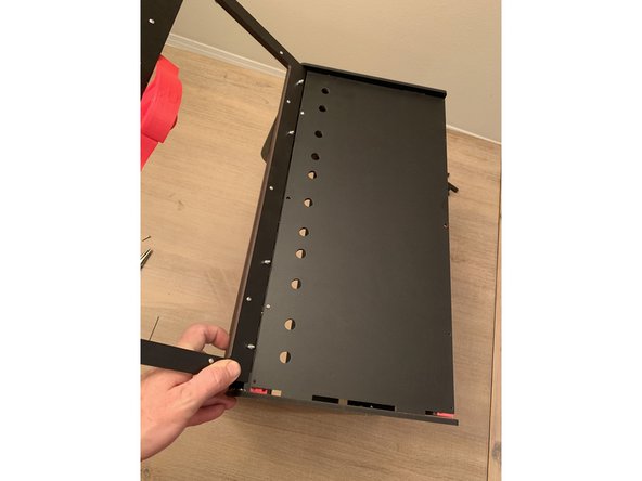
The next step is to set up 5 more brackets to hold the top and side panels to the rear panel. How you go about setting the nuts in them will depend on whether or not you intend to wall mount the unit or not.
-
If you do not intend to wall mount you will be affixing the brackets as shown in pic 3. If you do intend to wall mount the bracket will be flipped around in a vertically mirrored setup from what's pictured so as to hook atop the french cleat that will affix to the wall.
-
-
-
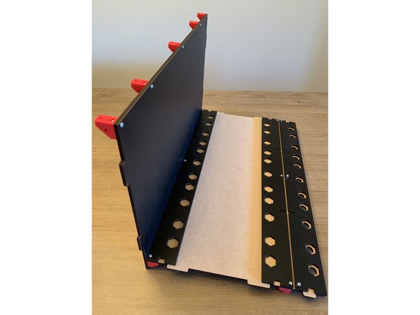
Note the seating points for the square nuts as shown in pic 1. If you're not wall mounting they will be pressed in the same locations as was done for the base brackets. Take care to add the extra square bolt on the two corner brackets in the same way as before.
-
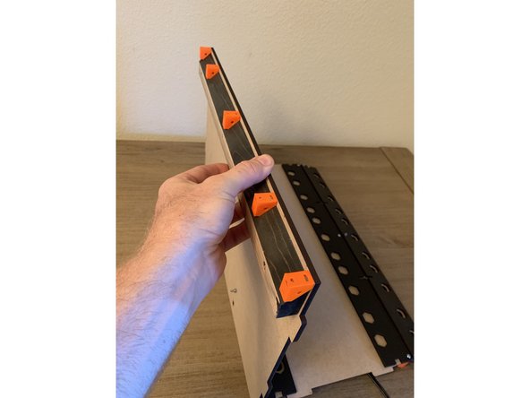
If you're WALL MOUNTING the rear brackets will be flipped around to act as the hooks over the wood wall cleat as shown in pic 3. Press the nuts into the corner of the bracket at the end where it runs perpendicular to the leg of the triangle as shown in pic 3. For more detail views of the wall mounting setup please see the wall mount guide.
-
If you think you may wish to wall mount your Repbox at some point we recommend assembling in the "hook" fashion shown in pic 3 so you have the option to easily wall mount later on. This is purely an aesthetic choice and will not compromise the overall integrity of the box.
-
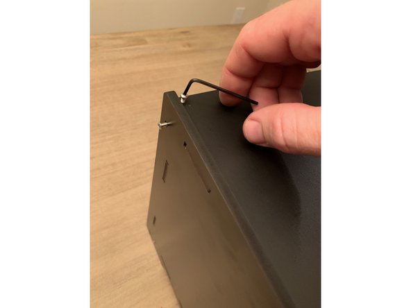
Once you've established orientation fasten the brackets to the top of the rear panel using 16mm screws. Repeat this 5 times and make sure to locate the brackets with the extra screws on the ends where the box corners will be.
-
If you have the Optional Humidity Hunter Kit, this is a good time to install the heater bar following the instructions provided here. ->
-
-
-
If you purchased your RepBox with the optional Humidity Hunter Kit you will have the version of the lid with the cutout for a hygrometer at the bottom corner. The assembly process for that lid is the exact same and the screws are in the same locations even though it doesn't look exactly like the plain lid pictured here. More Of Those Kit Details Shown Here.
-
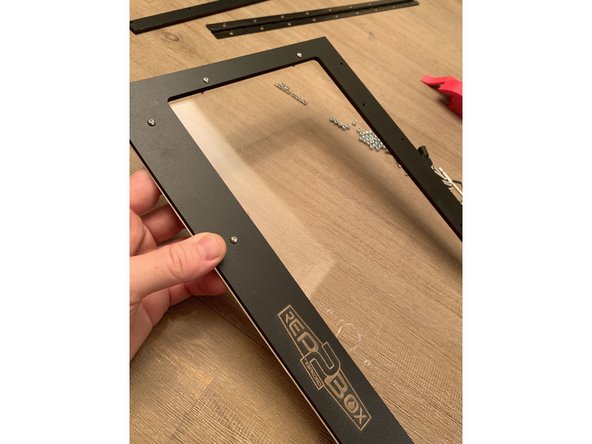
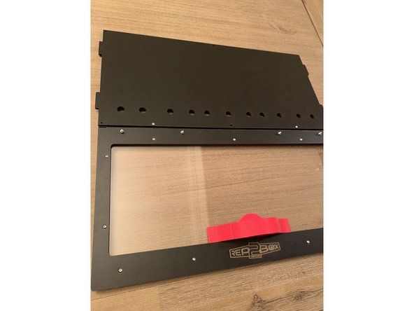
Next you'll be sandwiching the lid acrylic between the faceplate with the engrave on it and the rear lid seal bars as shown in these three photos.
-
Remove the paper from the acrylic lid prior to assembly.
-
TAKE CARE NOT TO OVER TIGHTEN THE SCREWS ON THE ACRYLIC BECAUSE IT CAN CRACK. IF YOU DO CRACK A PANEL AT ANY POINT DURING ASSEMBLY CONTACT SUPPORT@REPKORD.COM FOR A REPLACEMENT AT A DISCOUNT.
-
Press eleven (11) 16mm screws into the top of the faceplate and through the acrylic lid as shown in pic 1.
-
DO NOT PRESS SCREWS THROUGH THE VERY TOP FOUR HOLES OF THE LID WHERE THE HINGE WILL GO. THIS WILL BE DONE IN A LATER STEP.
-
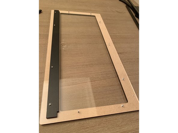
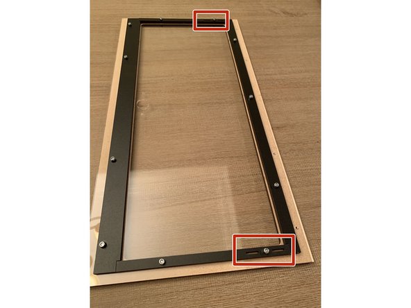
Press the lid seal bars on to the exposed screw posts as shown in pics 2 and 3. Notice the thicker of these bars goes at the bottom of the lid and the thinner on top.
-
For the side lid seal bars be sure to orient the rectangular cutouts towards the top of the lid as shown. This is where the lid prop eventually nests to keep the lid open.
-
-
-
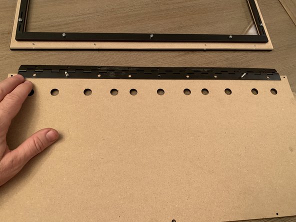
If you are configuring your RepBox2 with exit holes on the top as shown in pic 1. Decide whether or not you want those exit points at the front or rear of the box.
-
The unfinished side of the top panel faces the inside of the box. The photos are showing the top lid assembly turned upside down as if you were looking at it from inside the box.
-
We've decided in this configuration to orient the holes facing forward so we can place our Mosaic Manufacturing Palette 2 directly atop our RepBox in direct feed mode.
-
Press TWO (2) 16mm screws through from the top panel down and lay the continuous hinge on top. The center hole screw will be added in a later step.
-
IMPORTANT: Press the top hinge clamp onto the screws you set in the previous step and affix with two nylocks as shown in Pic 2 This is a commonly missed step and if the top hinge clamp is not added it will cause issues when the top panel is attached in a future step.
-
The hinge pin side should be FACE DOWN in this step so that the lid closes properly.
-
-
-
CRITICAL STEP: Please be sure to read this entire section carefully so your lid closes properly.
-
Next we attach the lid assembly to the top panel as shown in pic 1.
-
NOTE THAT THE FOUR (4) 16MM SCREWS THAT ATTACH THE HINGE TO THE LID ARE PRESSED THROUGH FROM THE INSIDE OF THE BOX OUTWARD. THIS IS CRITICAL FOR THE LID TO HAVE THE CLEARANCE TO CLOSE COMPLETELY.
-
Before tightening any of the screws on either side of the hinge you need to make sure the hinge is centered on both sides of the panel and that they're pressed together as tightly as possible. Any shifting or variance in this step may cause the lid not to close flush and rub on the side panels and/or lid props.
-
Once you're sure everything is centered and the lid and top panel are pressed as close to the hinge pin on each side as possible fasten the lid to the hinge using four (4) nylocks as shown in pic 2.
-
IF YOUR LID DOESN'T CLOSE PROPERLY LOOSEN THE SCREWS ON BOTH SIDES OF THE HINGE AND ADJUST THE HINGE POSITIONING AS NEEDED.
-
-
-
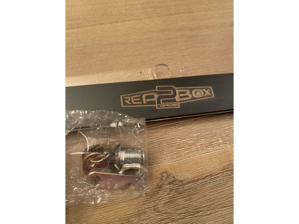
The latch mechanism pictured is only included with the seal kit. If you do not have the seal kit simply press fit the square nuts into the side of the lid handle and proceed to the next step.
-
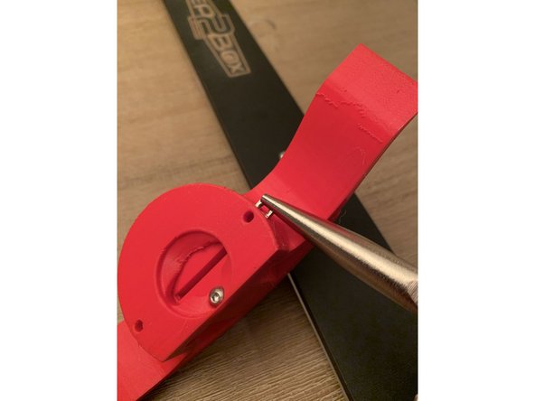
IF YOU HAVE THE SEAL KIT: Newer latch sets may have a black cover over the key. If the key doesn't fit in your handle or you are printing your own make sure you print the handle set that says "BLACK KEY" on it in the Ultra Latch folder. PRINT FILES ARE HERE
-
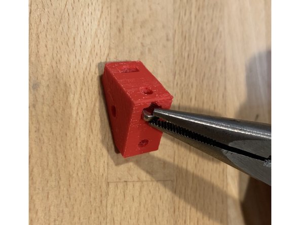
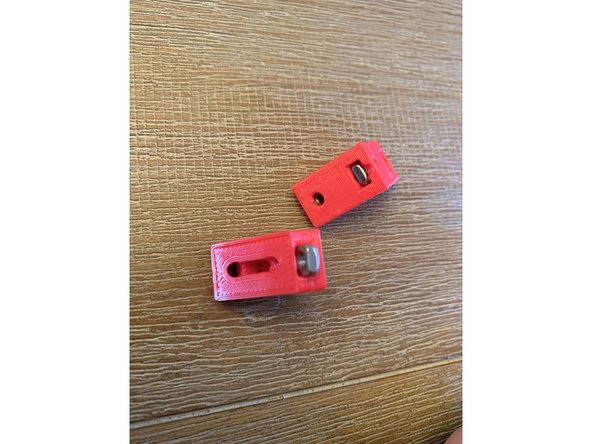
The 3D printed handle comes printed in place with small anchors to hold the front latch to the rear. If you have the seal kit you need to break those connections free by grabbing the front and rear handles with each hand and rotating in opposite directions. Cut the connections with flush cutters or a hobby knife to release more easily.
-
If your handles are already detached and you do not have the seal kit, run a 16mm screw through the bottom hole of each handle to affix.
-
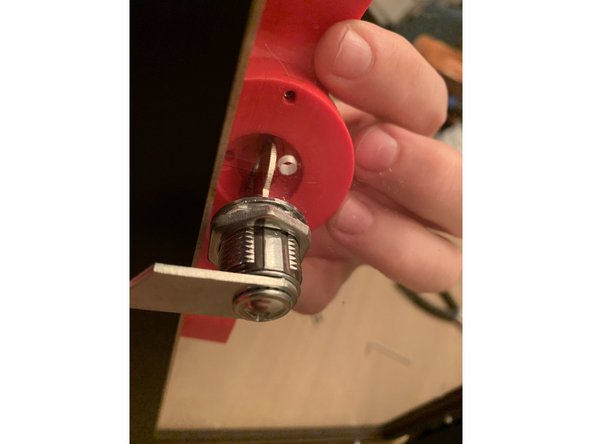
Press two (2) square nuts into the nut traps at the sides of the handle as shown in pic 1.
-
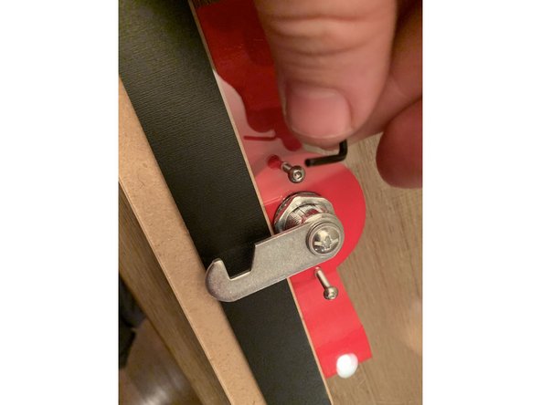
If you have the seal kit install the key latch as shown in pic 3 with the box in the locked position when the key is horizontal.
-
Slip the lid handle assembly over the key as shown in pic 3 and then fasten to the acrylic lid with two (2) 16mm screws.
-
TAKE CARE NOT TO OVER TIGHTEN THE SCREWS ON THE ACRYLIC BECAUSE IT CAN CRACK. IF YOU DO CRACK A PANEL AT ANY POINT DURING ASSEMBLY CONTACT SUPPORT@REPKORD.COM FOR A REPLACEMENT AT A DISCOUNT.
-
-
-
If you do not have the seal kit then you will just affix the handle to the lid as shown below without the latch shown in pic 1.
-
With the latch in the locked position as pictured, slide the nested together handles over the horizontally oriented key and run two 16mm screws through the seated square nuts from the backside of the lid to attach.
-
TAKE CARE NOT TO OVER TIGHTEN THE SCREWS ON THE ACRYLIC BECAUSE IT CAN CRACK. IF YOU DO CRACK A PANEL AT ANY POINT DURING ASSEMBLY CONTACT SUPPORT@REPKORD.COM FOR A REPLACEMENT AT A DISCOUNT.
-
Once the handle is attached the lid assembly is complete!
-
-
-
If you have custom sidepanels, Lay them on the outside of each of the melamine panels prior to running the 16mm screw through to attach the bracket.
-
Add a square nut to the top and center holes of one of the mega brackets and align as pictured with the side panel facing you.
-
Run a 16mm screw through from the backside of the side panel to affix the bracket. Repeat this process MIRRORED for the other side.
-
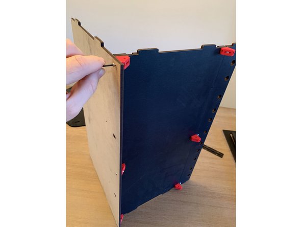
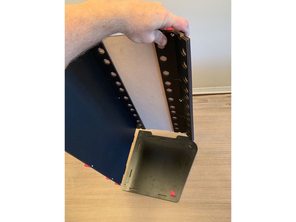
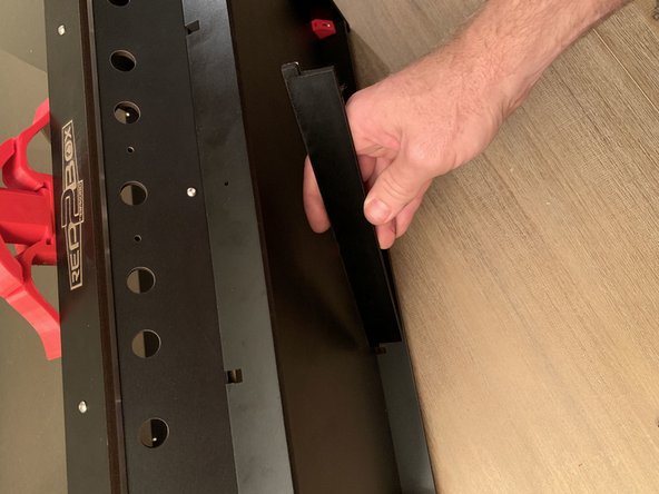
Lay the side panel with the bracket attached as pictured on the table and insert the base and rear panel assembly from earlier.
-
Insert the center track guide before placing the other side panel on top of the assembly.
-
-
-
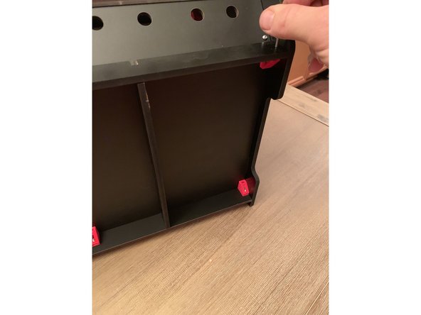
Place the other sidepanel atop the assembly as shown in these pics.
-
IF YOU HAVE CUSTOM SIDE PANELS LAY THEM ON TOP OF THE MDF PANELS PRIOR TO RUNNING THE 16mm SCREWS THROUGH TO FASTEN EVERYTHING TOGETHER.
-
ONLY FASTEN THE BOTTOM TWO CORNERS OF EACH SIDEPANEL FOR NOW
-
-
-
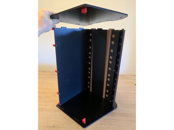
Bend the tops of the sidepanels out slightly to allow the top panel and lid assembly to fall into place and press their tennons into the corresponding cuts at the top of each sidepanel
-
Fasten the top panel to each of the brackets installed on the back of the rear panel using five (5) 16mm screws.
-
Fasten the top panel to the brackets installed to the top front of the sidepanels in step 14. Take care not to overtighten as it may crack the corners of the top sidepanels.
-
THE HOLE IN THE CENTER REAR OF THE TOP PANEL IS LARGER THAN THE REST. THIS IS NORMAL. JUST FASTEN AS YOU DO WITH THE REST FOR NOW AND DON'T OVERTIGHTEN.
-
-
-
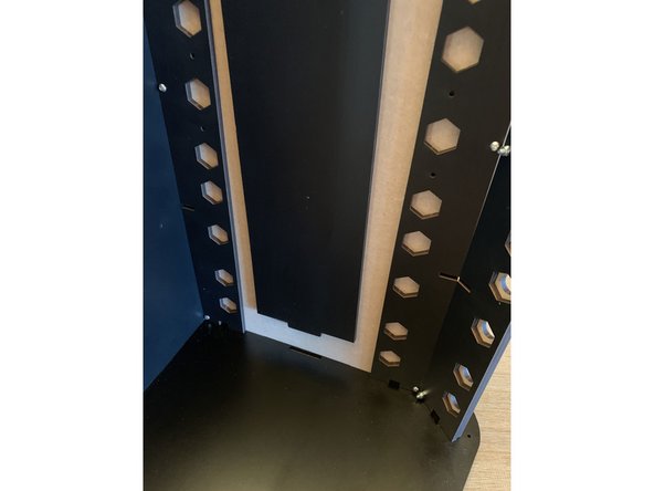
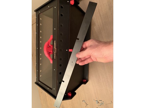
LOOSELY Screw the base reinforcement bar in place on the front 3 brackets on the base panel as pictured. Just enough to hold it in place.
-
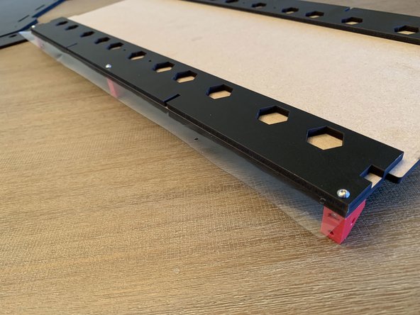
Run the base crossmembers from the notch in the rear panel to the front reinforcement bar as pictured. The larger notch goes into the reinforcement bar at the front of the box.
-
Tighten the 3 screws for the reinforcement bar the rest of the way to prevent the crossmembers from falling out.
-
-
-
NOTE: After August 2019 RepBox 2 now includes a single steel lid prop instead of the 3D printed ones shown here. You may still chose to print the lid prop(s) if you wish but the steel prop is more robust and reliable. It may be installed on whichever side you prefer.
-
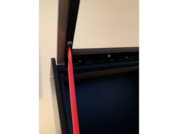
If using the 3D Printed lid props attach to BOTH sidepanels using a 16mm screw and a nylock as in pic 1. They should bolt to the INSIDE of the panel with the flange laying over the edge of the sidepanel. If using the provided steel prop simply pick which side works best for you.
-
DO NOT OVERTIGHTEN THE NYLOCK. MAKE IT JUST SNUG ENOUGH TO MAINTAIN SLIGHT FRICTION ON THE PROP BUT STILL ALLOW IT TO MOVE INTO POSITION FREELY.
-
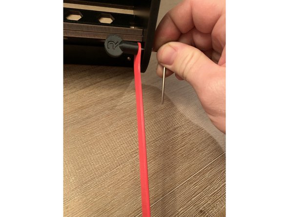
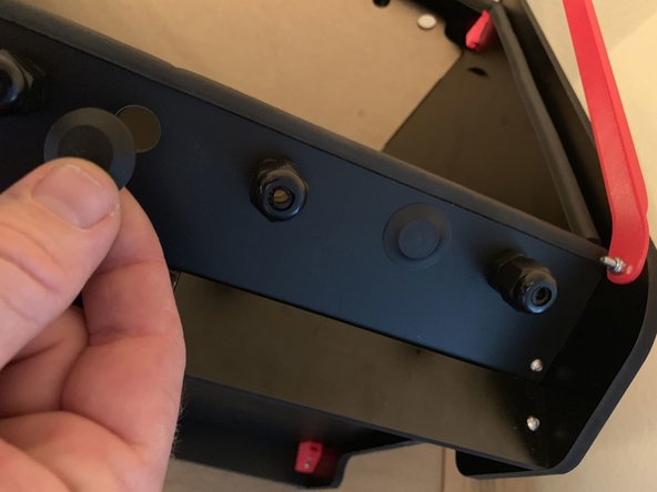
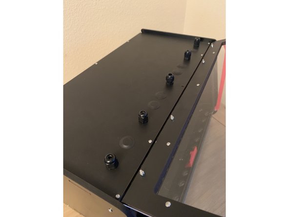
Position the exit fittings and plugs as desired. The kit includes fittings for 6 exit points and plugs for the rest of the holes. Additional plugs and fittings may be purchased at repkord.com.
-
-
-
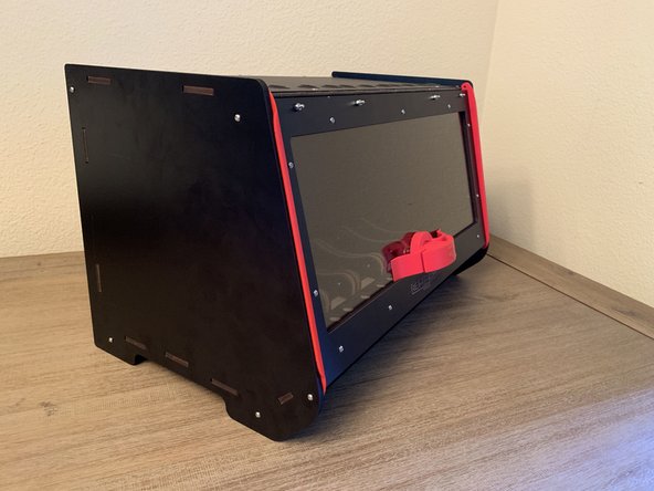
Nice job! The main box assembly is complete! Have a RepSaver to celebrate! Time to move on to the roller assembly here >
-
For Optional Seal Kit Instructions See the Separate Guide on the Main Menu or continue on HERE
-


Cancel: I did not complete this guide.
5 other people completed this guide.

6 Comments
Here is a new Step by Step Assembly video. It will follow these steps and make it much easier to build your new Repbox 2! https://youtu.be/nZ5MGGcn6jw
Jim Edgeworth - Resolved on Release Reply
After step 15, when we “ONLY FASTEN THE BOTTOM TWO CORNERS OF EACH SIDEPANEL FOR NOW” when were we supposed to do the top corner screws?
Phil Kelly - Resolved on Release Reply
There are many cut out parts that appear to be for the spools, no instructions for assembly. Are there any official assembly instructions provided by the manufacturer?
Jonathan Smith - Resolved on Release Reply
Those directions are in the next stage and linked at the bottom of the page. 2 - Roller Assembly
ThePooch -
This guide is hard to follow as the parts are not labeled. Thumbs down
Jonathan Smith - Resolved on Release Reply