
-
-
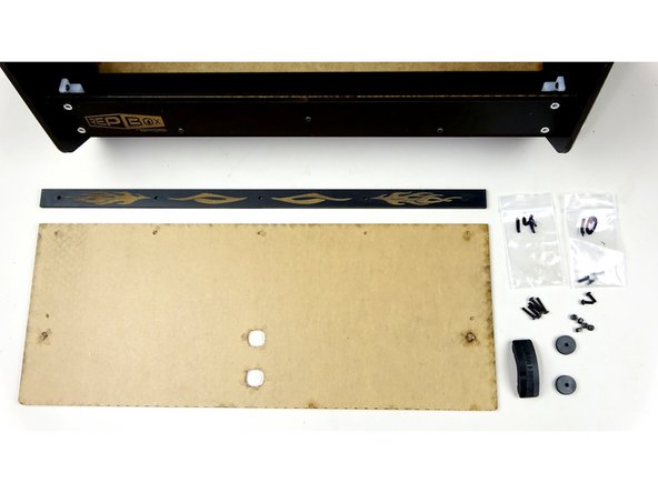
Lid Stay Hinges (One complete, one missing the end mount)
-
25mm Bolts, Washers, Nylock Bolts.
-
Laser Cut Circular Standoffs
-
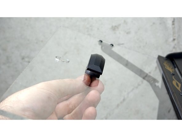
One 3D Printed Bushing from the roller parts bag.
-
10mm Bolt, Nylock, washers
-
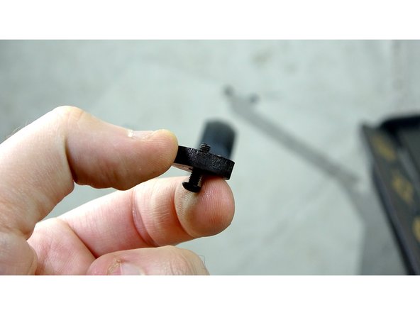
Loose End Mount
-
For the Seal Kit the 4x Laser etched spacers will be integrated into the NEW 3D Printed parts installed earlier.
-
-
-
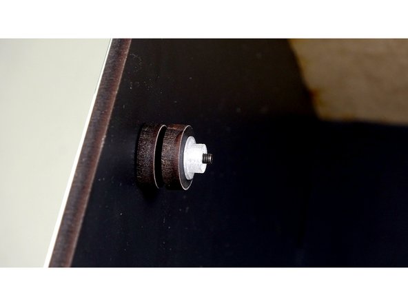
Insert a 25mm Bolt through the right Graphic side panel, to inside of the inner compartment.
-
Place two of the Laser Cut standoffs on the bolt.
-
Grab the Hinge that has the end mount already attached.
-
-
-
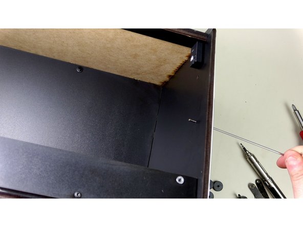
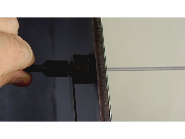
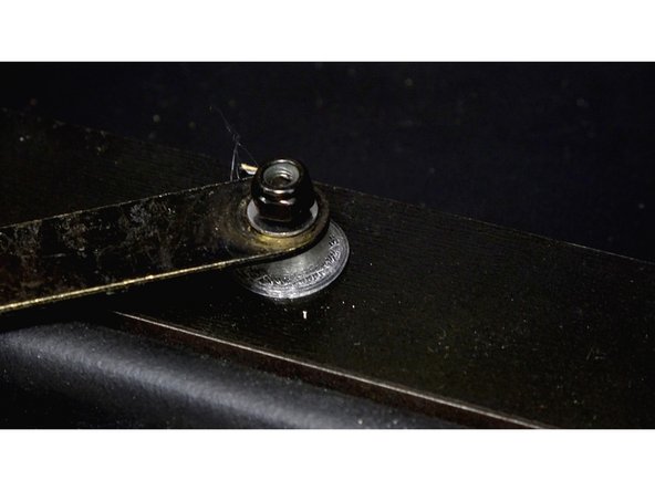
Insert a 25mm Bolt through the right Graphic side panel and the Seal bar(not pictured), to the inside of the inner compartment.
-
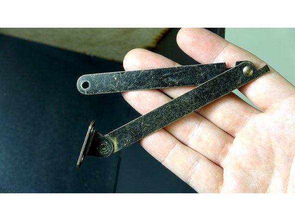
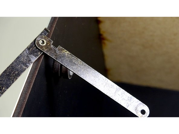
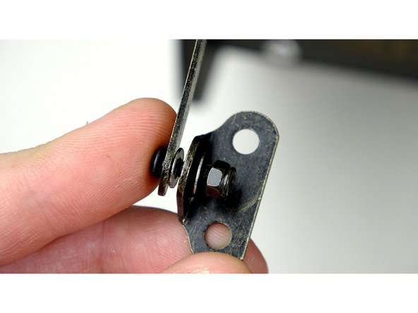
Grab the Lid Hinge with the end mount intact. It The second picture shows the orientation that it will be installed.
-
-
-
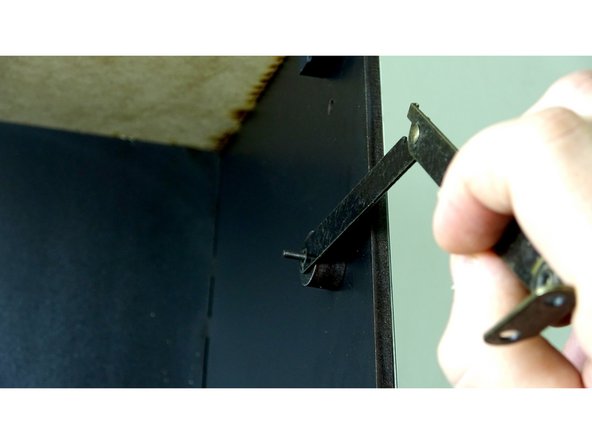
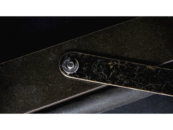
Place the Hinge over the bolt, followed by a washer.
-
Pay close attention to the orientation of the Hinge. It should fold upward like in the first picture.
-
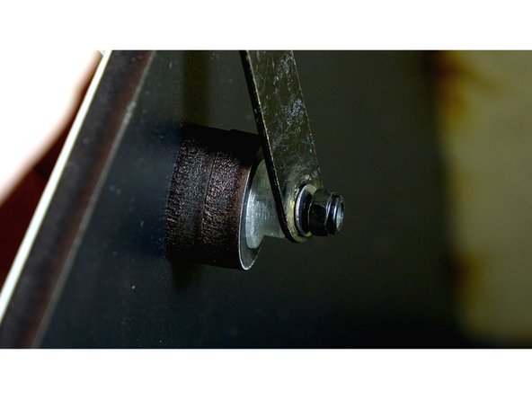
Place a nylock nut on the bolt and tighten down just enough to make contact with the arm.
-
Do NOT tighten to the point the arm does not move.
-
For the Seal Kit the 4x Laser etched spacers will be integrated into the NEW 3D Printed parts installed earlier.
-
-
-
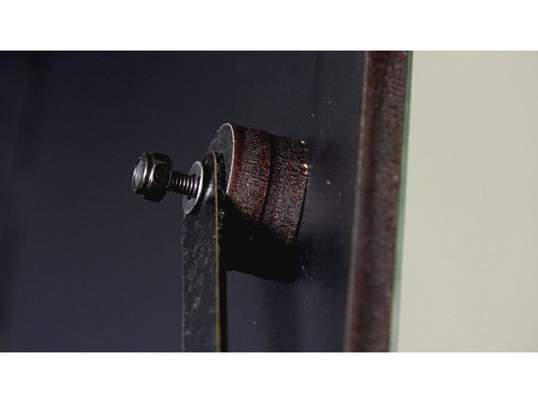
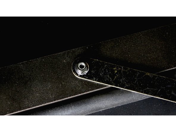
Place the arm onto the bolt, followed by a washer.
-
Secure into place using a nylock nut.
-
Tighten down just enough to make contact with the arm. Do NOT tighten to the point the arm does not move.
-
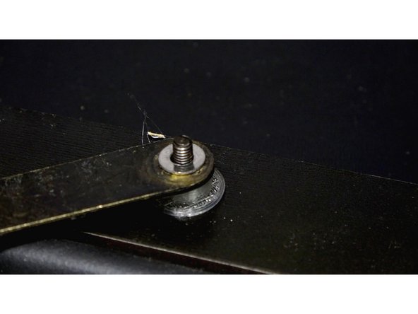
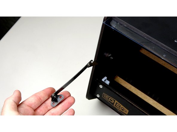
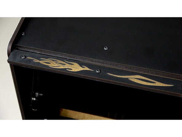
The last picture is of the standard kit, but shows proper arm orientation.
-
-
-
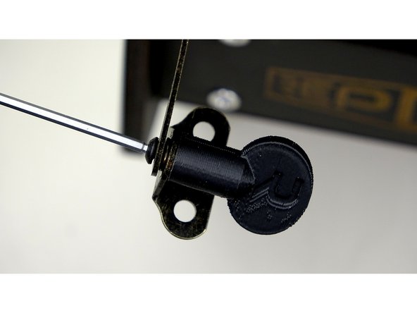
On the left side, insert a 25mm bolt like on the right side.
-
Put two laser cut spacers over the bolt, followed by a 3D Bushing.
-
Place the arm on the bolt, followed by a washer.
-
Secure the arm in place with a nylock.
-
Tighten down just enough to make contact with the arm. Do NOT tighten to the point the arm does not move.
-
-
-
Insert 25mm bolt through the graphic panel, through the seal bar.
-
Place a 3D Bushing on the bolt.
-
Put the arm on the bolt, followed by a washer.
-
Secure the bar on with a Nylock.
-
Tighten down just enough to make contact with the arm. Do NOT tighten to the point the arm does not move.
-
-
-
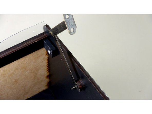
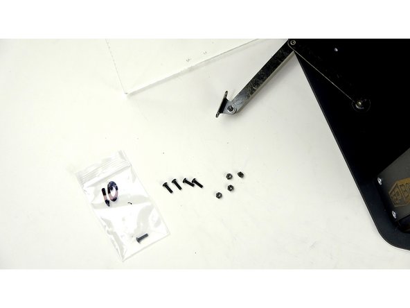
Insert a 10mm bolt through the end of the left Hinge arm
-
But a washer on the bolt, followed by the End Mount and another washer.
-
Secure the End Mount in place with a nylock. Do NOT over tighten. It needs to move freely.
-
Tuck both the left and right Hinge arms back into the interior of the box for now.
-
-
-
Acrylic Panel
-
Acrylic Lid Clamp Panel
-
14mm bolts, 10mm bolts, Nylock Nuts
-
Laser Cut Wood Spacer (1 for Seal Kit, 2 for Standard Kit)
-
3D Printed Handle
-
SEAL KIT: 3D Printed Handle, Lock and Key kit
-
-
-
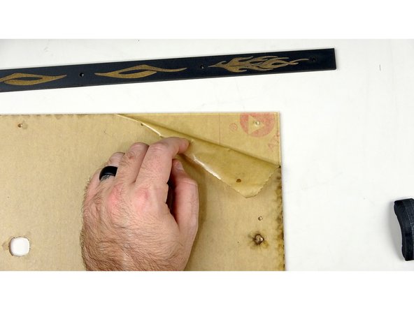
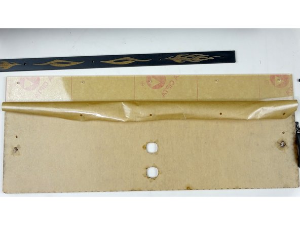
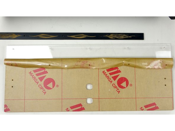
Carefully peel back the protective film to expose the top of the acrylic. Repeat for the back as pictured.
-
The amount exposed should be just a little more than the width of the Acrylic Lid Clamp on both sides.
-
Leave the rest of the film on for now to protect the acrylic during install.
-
-
-
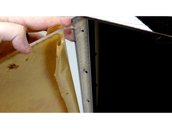
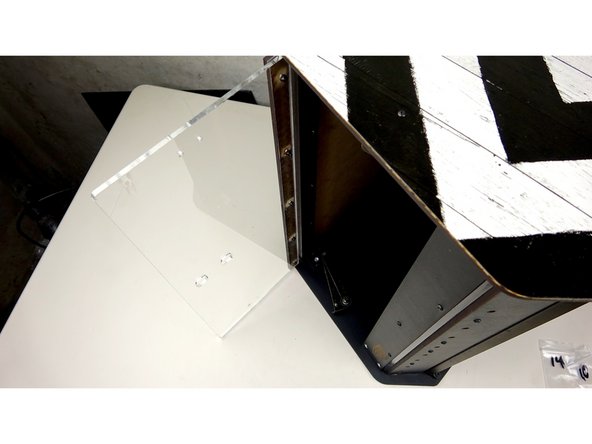
This next step is easier if the box is on its side.
-
Take the Acrylic Clamp panel and line it up with the vinyl on top of the box.
-
Start threading through 14mm bolts from the top of the Clamp panel, trough the vinyl.
-
Line up the Acrylic panel and thread the bolts through the holes on the panel.
-
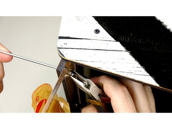
Secure in place with Nylock nuts. (A pair of needle nose pliers may work better than the hex key for this step)
-
Be Careful not to over tighten the nylock nuts! It could break the acrylic!
-
-
-
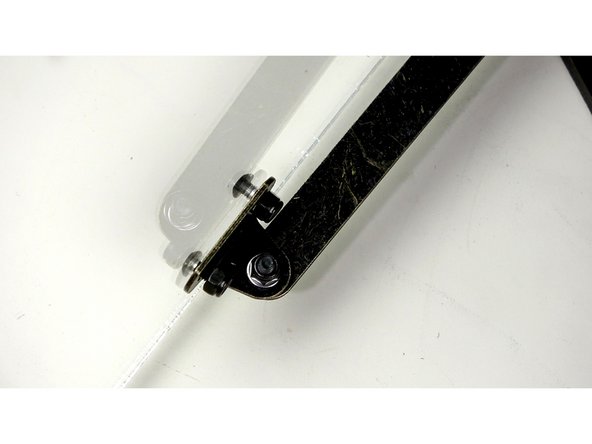
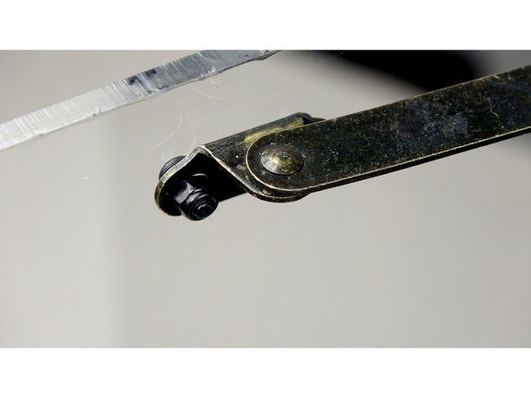
Remove the rest of the protective film from the acrylic.
-
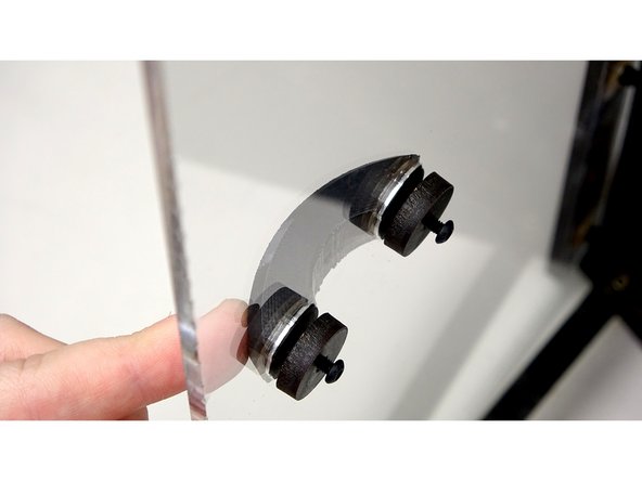
Using 10mm bolts and Nylock nuts, secure the Hinge arms to the Acrylic as shown.
-
Be Careful not to over tighten the nylock nuts! It could break the acrylic!
-
-
-
Take two of the laser cut stand offs and two 10mm bolts. Put the bolts through the standoffs as pictured
-
Place the handle into the holes of the Acrylic lid.
-
Secure into place using the bolts and standoffs.
-
-
-
Put the handle that comes with the seal kit into the top large hole in the acrylic.
-
Attach with a 10mm bolt and a laser cut circular stand off.
-
-
-
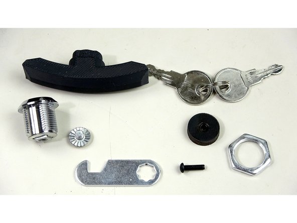
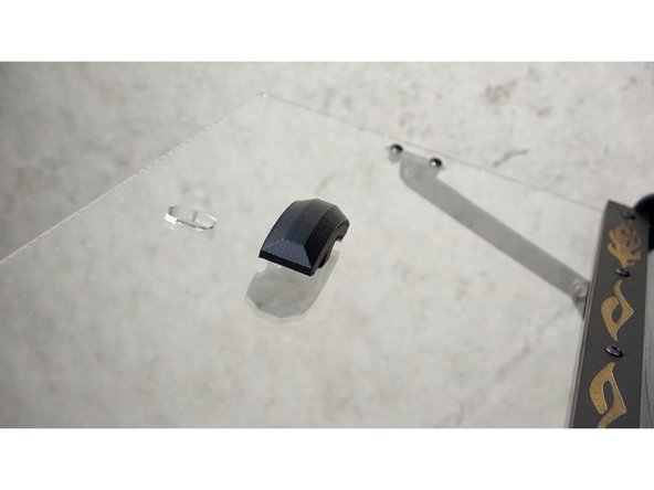
Disassemble the lock assembly.
-
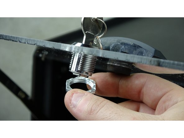
Insert the main assembly into the bottom hole. It helps to have the key in to check orientation. The key should be up and down.
-
Thread the nut over the lock assembly and secure it to the acrylic.
-
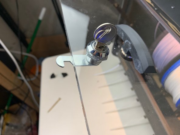
Attach the latching arm using the Phillips bolt that came in the same bag.
-
Check orientation.
-
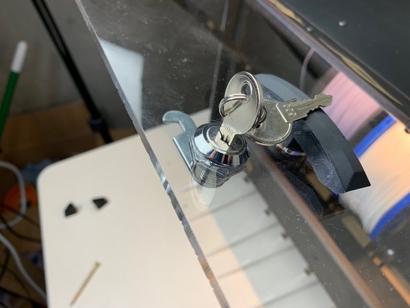
The last pic shows how the rotation should work. The latch should rotate from horizontal to vertical with a COUNTER CLOCKWISE turn and lock. Pay close attention to the notch orientation.
-
-


Cancel: I did not complete this guide.
One other person completed this guide.
