
Tools
Parts
No parts specified.
-
-
We highly recommend you use these three additional resources for the build:
-
Assembly Video: https://youtu.be/GhOFIa803xQ
-
Interactive CAD Model v2.5.0: https://repkord.com/RB2Model
-
Interactive CAD Model v2.5.1: https://repkord.com/RB251Model
-
Interactive CAD Model v2.5.2: https://repkord.com/RB252Model
-
Bill of Materials specific to the version being assembled.
-
-
-
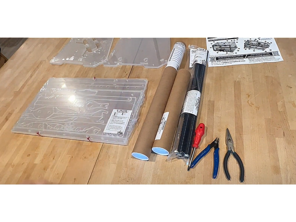
For this build you will need a phillips head screwdriver, flush cutters, and optionally some needle nose pliers.
-
The printed Bill of Materials is very helpful to the assembly process.
-
-
-
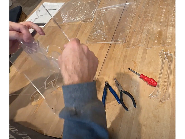
All clear acrylic panels come from the factory with a protective film on BOTH SIDES of the panel. Be sure to remove it all prior to assembly.
-
NOTE: The color of your protective film may be a different color than the clear you see here. This is normal. The acrylic underneath is still the same clear in the finished product.
-
-
-
The color of components included with the RepBox will vary based upon the 'flavor' purchased.
-
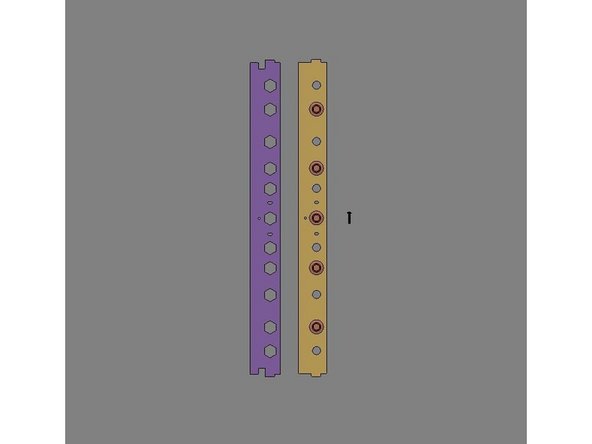
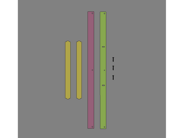
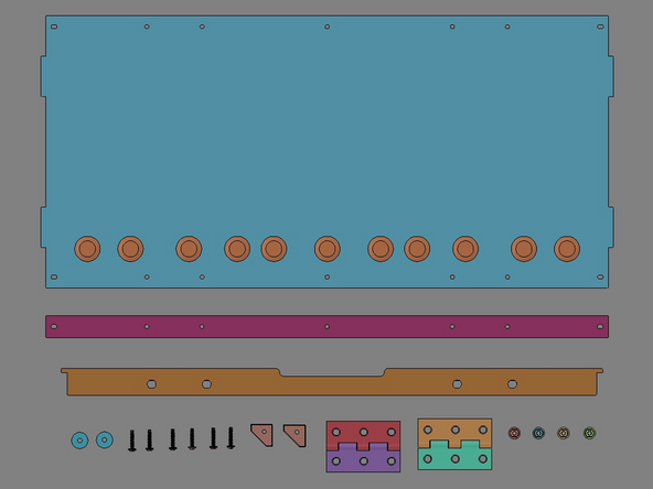
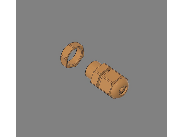
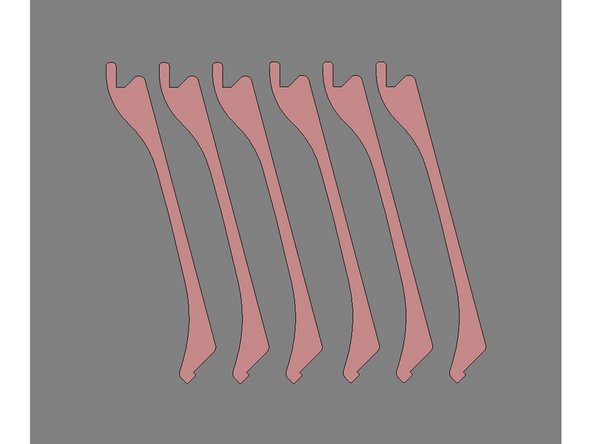
IMG 1 - Identify the six parts shown.
-
IMG 2 - Locate these two part sets. Each part is connected with small strips to keep them from becoming lost.
-
You can separate these parts from the strips either by hand or trimming them clean with flush cutters.
-
Suggestion: You can also leave the parts on the strips for the moment. Then just cut them loose right as they're needed.
-
-
-
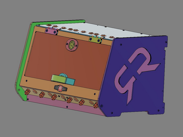
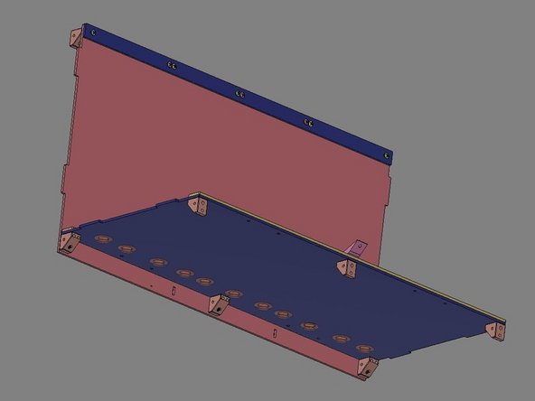
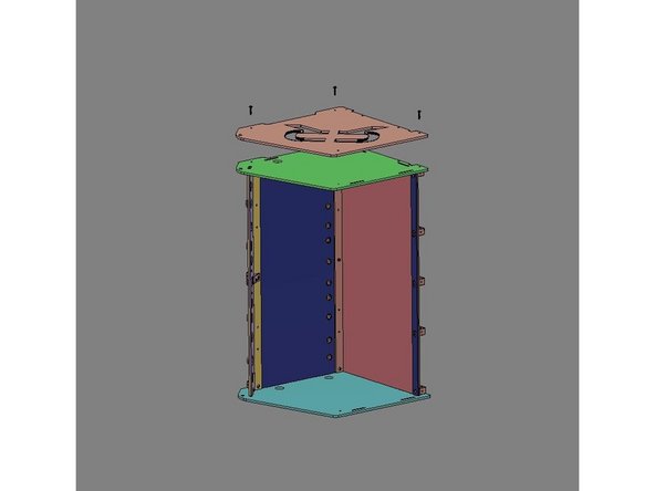
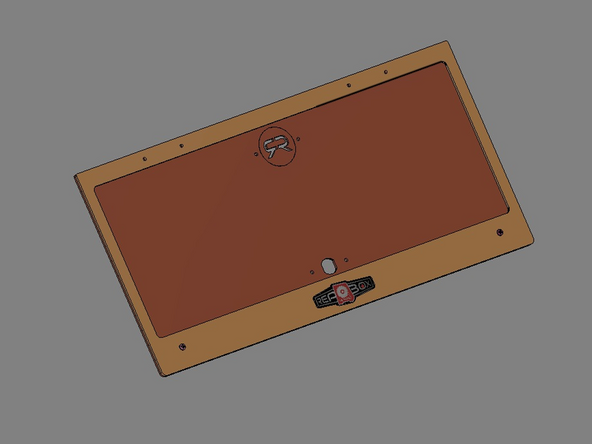
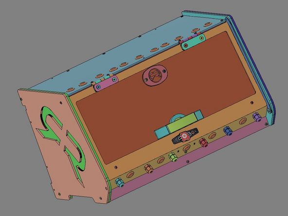
In the following instructions, all parts will shown in a contrasting color to help distinguish one part from another during assembly. The actual parts included with the kit will be Clear Acrylic.
-
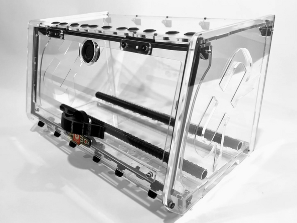
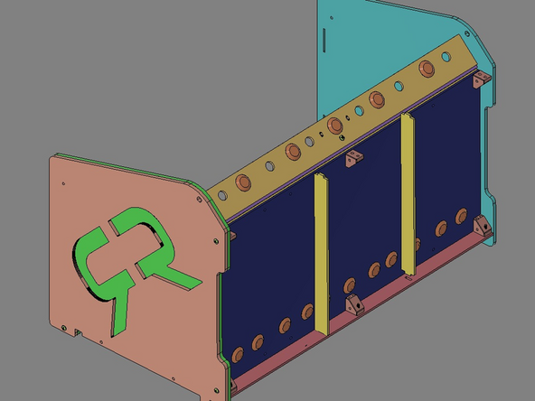
IMG 1 - RepBox shown in Clear Acrylic RepBox
-
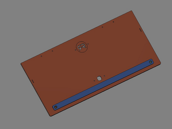
IMG 2 - RepBox shown in contrasting colors.
-
-
-
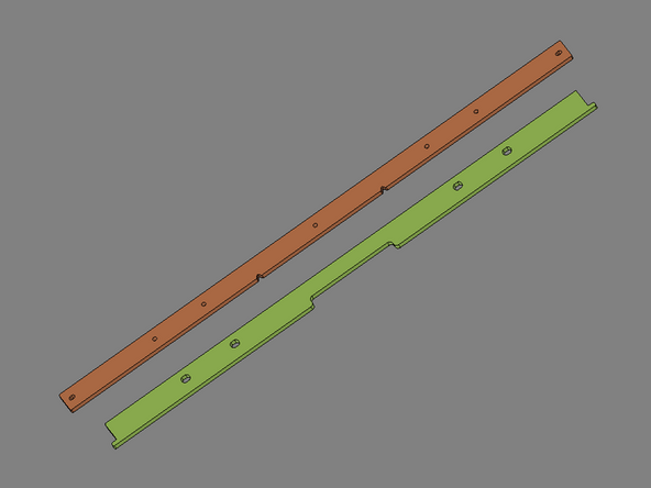
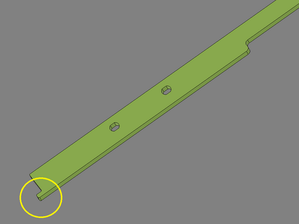
IMG 1 - Both of these parts (Item 18 & 26) are included within the Parts Tube if you have v2.5.0
-
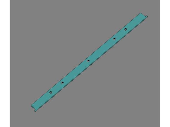
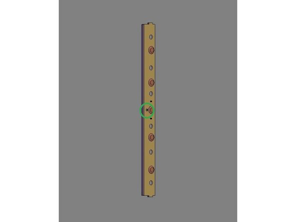
IMG 2 - This part (Item 26) is included within the Parts Tube if you have either v2.5.1 OR v2.5.2.
-
In either case, do not cut off the tabs (circled in yellow) on either end of Item 26.
-
-
-
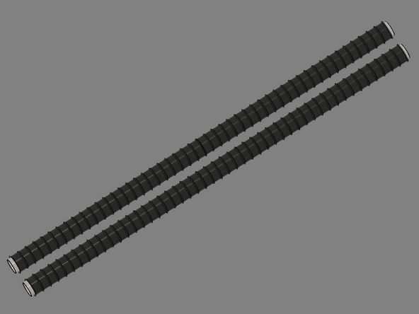
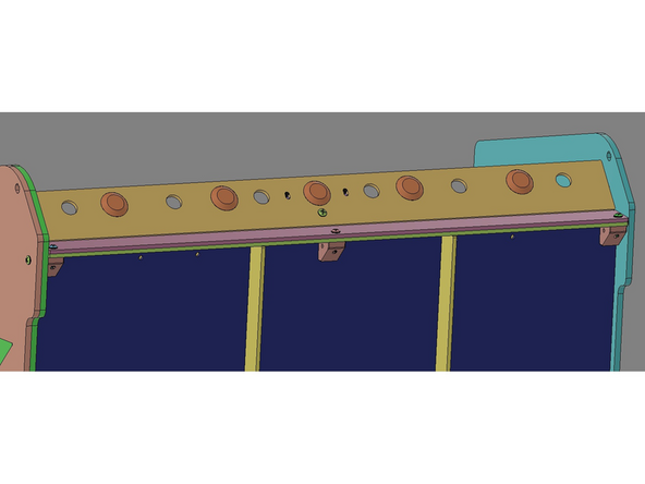
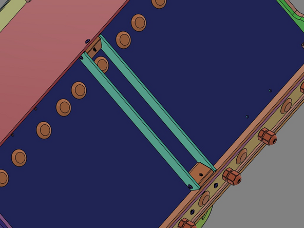
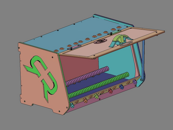
IMG 1 - Your RepBox comes equipped with our new Slip Rod system. It is designed so that you can easily move spools in/out of the box and reposition them simply. For the majority of plastic spools you should have a nice slick surface for them to slip & slide on.
-
IMG 2 - Additional Spool and Roller options!
-
-
-
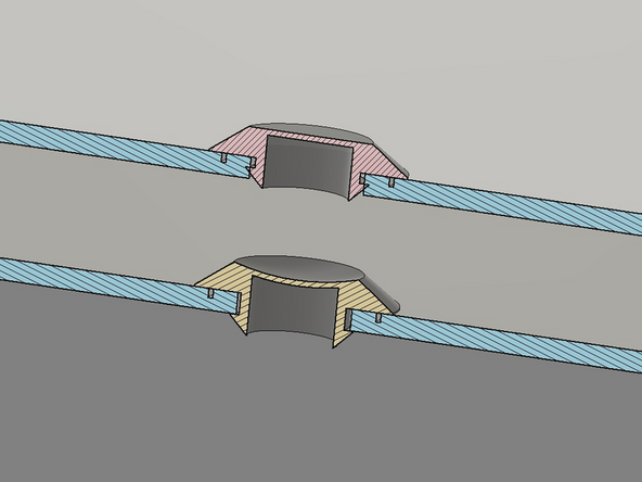
Please find a flat/rigid surface to install the hole plugs.
-
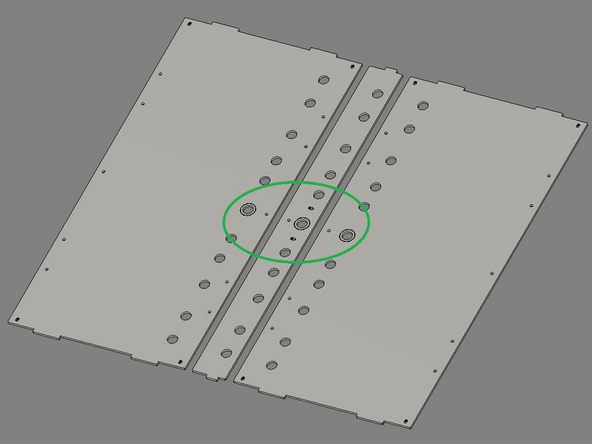
IMG 1 - Locate these three parts. Face the side with the circular engrave upward.
-
IMG 2 - Align the Exit Plug to the selected hole position.
-
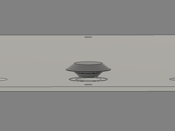
IMG 3 - Press (do not hammer) the Exit Plug into place with firm downward pressure towards the flat surface to get it started in the hole (see plug in Red/Top).
-
IMG 3 cont. - Lift the panel off the table and support it from the back side with your fingers, then depress the center of the Exit Plug to finish the installation (see plug shown in Yellow/Bottom).
-
The default pattern for these plugs is shown in the Assembly Video, but can be positioned anywhere as necessary.
-
-
-
Do Not Use Power Tools for assembly.
-
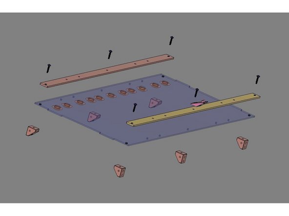
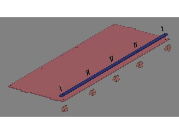
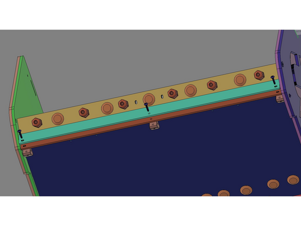
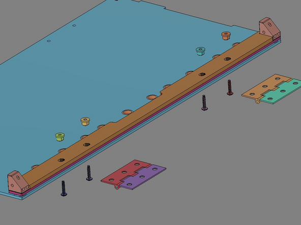
NOTE: - These images will vary based upon the version being built. The parts shown here are for v2.5.0 and v2.5.1. The v2.5.2 will use x2 2B Bottom Spacer Bars with only three holes, but will be assembled in the same way.
-
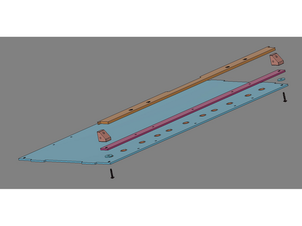
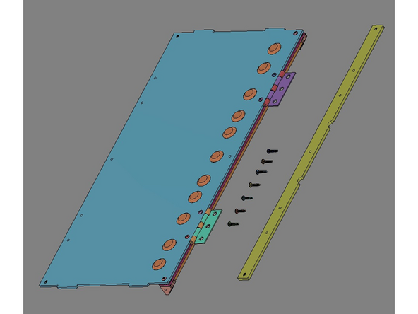
IMG 1 - Locate x2 Spacer Bars and align them to the Bottom Panel as shown. Have x6 Brackets, x6 TF Screws and the Exit clip ready for assembly.
-
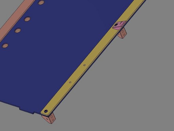
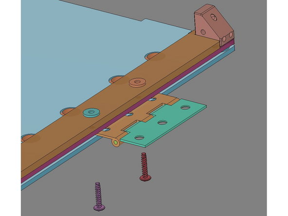
IMG 2 - Install the TF Screws through the Spacer Bars and Base Assembly, then into the Brackets. For the Front/Center location, include the Exit Clip oriented as shown.
-
Do not fully tighten these screws, just bring them down flush. The Brackets should be available to rotate (if necessary) for subsequent steps.
-
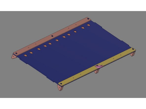
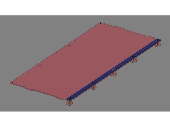
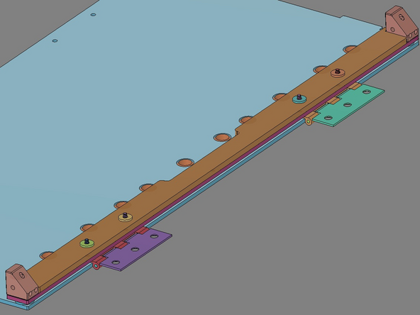
IMG 3 - This is the finished Base Assembly. Please confirm that all parts are oriented correctly.
-
-
-
Do Not Use Power Tools for assembly.
-
NOTE: - These images will vary based upon the version being built. The parts shown here are for v2.5.0. The v2.5.1 and v2.5.2 will use a different version of the Rear Panel, but will be assembled in the same way.
-
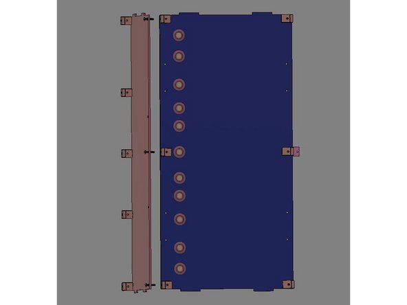
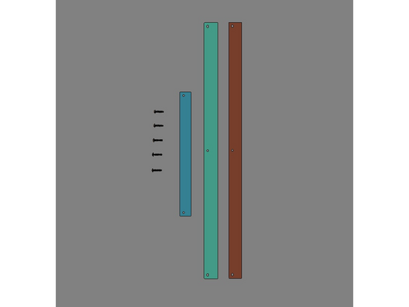
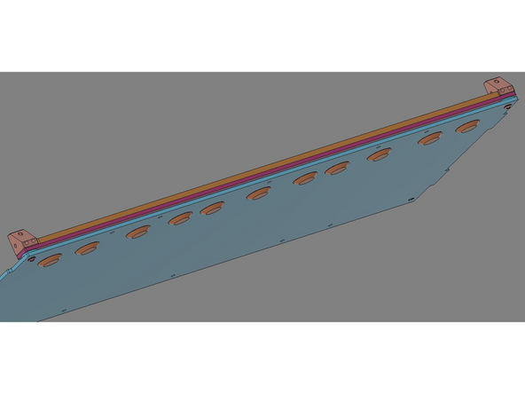
IMG 1 - Locate the Rear Reinforcement Bar and align it to the Rear Panel as shown. Have x5 Brackets and x8 TF Screws ready for assembly.
-
Install the TF Screws through the Rear Reinforcement Bar and Rear Panel, then into the Brackets.
-
Do not fully tighten these screws, just bring them down flush. The Brackets should be available to rotate (if necessary) for subsequent steps.
-
IMG 2 - This completes Part 1 of Base Assembly. Please confirm that all parts are oriented correctly.
-
-
-
Do Not Use Power Tools for assembly.
-
NOTE: - These images will vary based upon the version being built. The parts shown here are for v2.5.0. The v2.5.1 and v2.5.2 will use a different version of the Rear Panel, but will be assembled in the same way.
-
IMG 1 - Have x3 TF Screws ready for assembly.
-
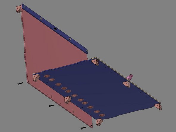
IMG 2 - Bring the Rear Panel and Base Assembly together and secure them with x3 TF Screws.
-
Standing the two halves up vertically might make this process a bit easier (as shown in IMG 2). Start with the top-most screw, then the middle and finally the bottom.
-
IMG 3 - Please confirm that all parts are oriented correctly.
-
-
-
Do Not Use Power Tools for assembly.
-
NOTE: - These images will vary based upon the version being built, but will be assembled in the same way.
-
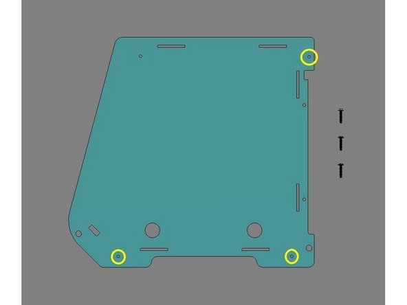
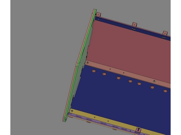
IMG 1 - Locate x1 Inner Side Panel and x3 TF Screws. These three screws will be inserted into the holes (highlighted with the Yellow circles).
-
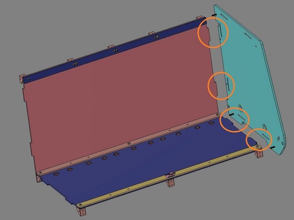
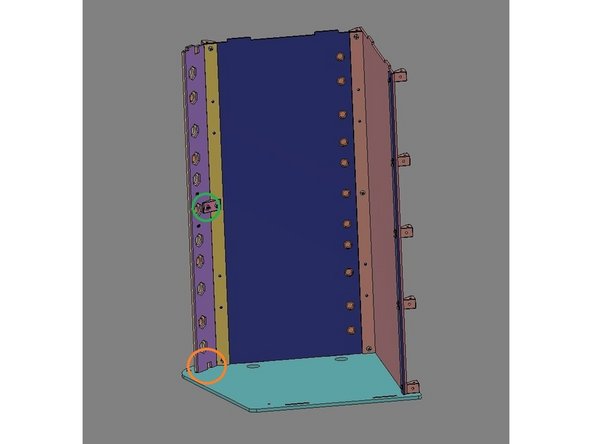
IMG 2 - Align the Inner Side Panel with the Main Assembly as shown. Fasten the Inner Side Panel with the x3 TF Screws. Utilize the alignment features (highlighted with Orange circles).
-
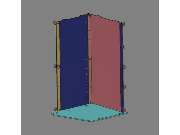
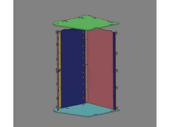
IMG 3 - Carefully stand the assembly up on end in preparation for the nest step.
-
Be careful not to scratch the Side Panel. We suggest setting the assembly a few sheets of paper/other to help protect it.
-
-
-
Do Not Use Power Tools for assembly.
-
NOTE: - These images will vary based upon the version being built, but will be assembled in the same way.
-
IMG 1 - Locate the Outer Exit Panel (from Step 1), the Inner Exit Panel and x1 TF Screw.
-
IMG 2 - Align the two panels together using the TF Screw for reference.
-
All holes should be in alignment.
-
IMG 3 - Insert this panel stack into the Main Assembly using the alignment features on the Inner Side Panels (highlighted with an Orange circle).
-
IMG 3 cont. - Finally, secure the panel stack using the TF Screw from the outside, going through both panels, into the Exit Clip (highlighted with Green circle).
-
-
-
Do Not Use Power Tools for assembly.
-
NOTE: - These images will vary based upon the version being built, but will be assembled in the same way.
-
IMG 1 - While the main assembly is still up on end, locate the other Inner Side Panel. Lower it onto the Main Assembly using the alignment features as was done in Step 6.
-
IMG 3 - Locate x1 Outer Side Panel and x3 TF Screws. Align the Outer Side Panel with the Inner Side Panel and insert the three screws as was done in Step 6.
-
IMG 3 - Do not tighten these three screws yet. There needs to be a small gap between the Side Panels and the Main Assembly.
-
Tighten these screws just enough to ensure the alignment features are engaged.
-
-
-
Do Not Use Power Tools for assembly.
-
NOTE: - These images will vary based upon the version being built, but will be assembled in the same way.
-
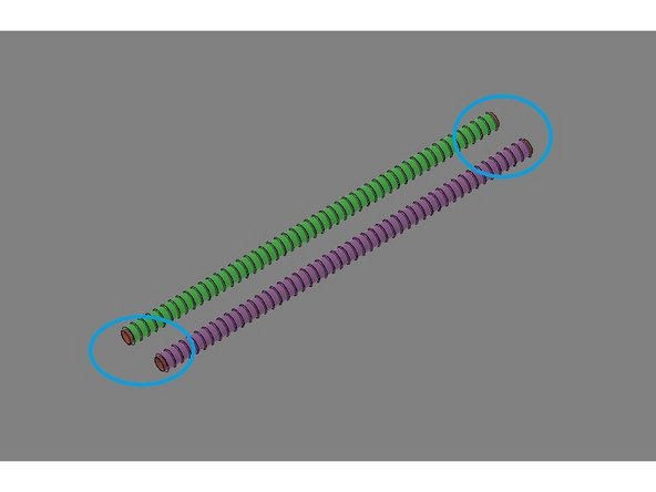
IMG 1 - Locate the Slip Rod Pack. Confirm that both have exposed metal tube on each end (highlighted with Blue circles). If they don't, make small adjustment to the slip covers so they do.
-
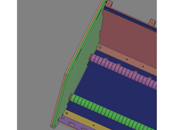
IMG 2 - Insert one end of each Slip Rod into the Inner Side Panel on the 'far' side of the Main Assembly. Then lower the 'near' end down into the assembly and align them with their holes. The gap left during the previous image might need to be opened/closed to allow for good fit.
-
IMG 3 - Once the Slip Rods are inserted, tighten the two lower TF Screws (nearest to the Slip Rods) to secure the Slip Rods and close the gap at the bottom.
-
Do no tighten the upper most screw yet.
-
Stand the Main Assembly up on end (Double R's down) in preparation for the next step.
-
-
-
Do Not Use Power Tools for assembly.
-
NOTE: - These images will vary based upon the version being built, but will be assembled in the same way.
-
IMG 1 - Remove the x3 TF Screws installed in Step 5, but leave the Inner Side Panel in place.
-
IMG 2 - Locate the remaining Outer Side Panel and align it with this existing Inner Side Panel.
-
IMG 3 - Re-install the x3 TF Screws into their original holes to secure both panels to Main Assembly.
-
-
-
Do Not Use Power Tools for assembly.
-
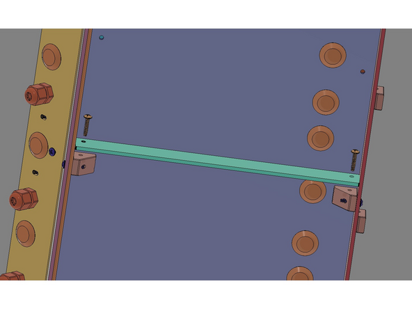
IMG 1 - Locate x2 Base Stringers, the Base Face Plate, the Stringer Support Bar and x3 TF Screws.
-
IMG 2 - Lay the Main Assembly on it's back. Install the Base Stringers by using the alignment features as shown.
-
IMG 3 - Stack the Base Face Plate onto the Stringer Support Bar and align their holes. This stack can now be added the Main Assembly by aligning the holes with the holes in the Brackets. The Base Stringers will align into the slots of the Stringer Support Bar. Install the x3 TF Screws as shown.
-
This completes the Main Assembly. Set it aside for the subsequent steps.
-
-
-
Do Not Use Power Tools for assembly.
-
IMG 1 - Locate x1 Base Stringer, the Base Face Plate, the Stringer Support Bar and x5 TF Screws.
-
IMG 2 - Lay the Main Assembly on it's back. Stack the Base Face Plate onto the Stringer Support Bar and align their holes. This stack can now be added the Main Assembly by aligning the holes with the holes in the Brackets and securing them with x3 TF Screws.
-
IMG 3 - Align the Base Stringer will the holes in the Brackest installed on the Main Assembly and secure them with x2 TF Screws
-
This completes the Main Assembly. Set it aside for the subsequent steps.
-
-
-
Do Not Use Power Tools for assembly.
-
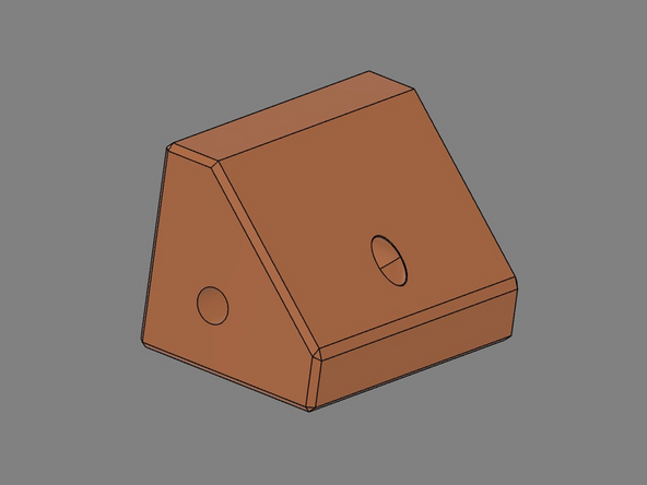
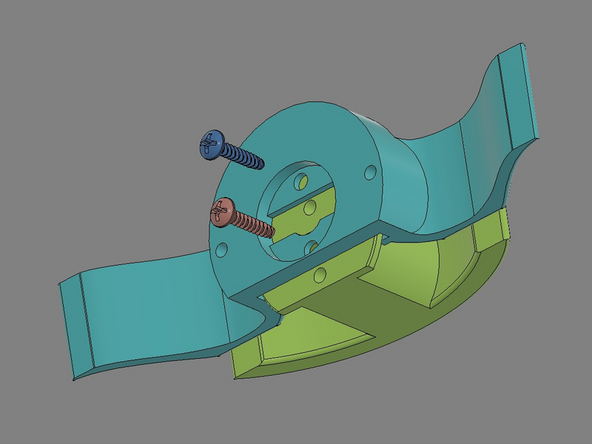
IMG 1 - This is the Fat Man bracket. It is available for free download at Printables.com - https://www.printables.com/model/353447-....
-
In the 2.5.2 kits, you received x2 Base Stringers. While the standard Bracket included in the kit will only accommodate one Base Stringer, the new Fat Man will accommodate two Base Stringers.
-
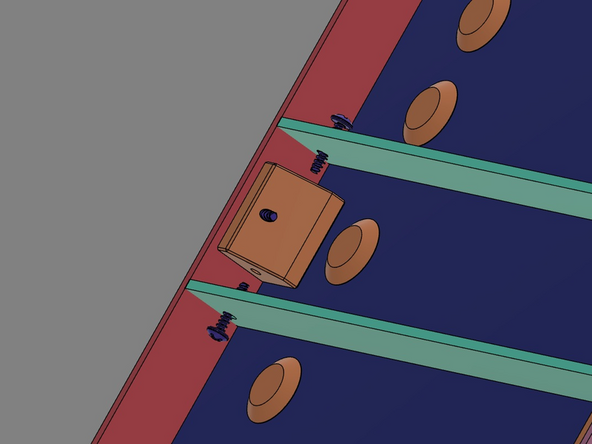
IMG 2 - The Fat Man will install exactly like the original Bracket (shown in the previous step),
-
IMG 2 cont. - The Base Stringers can now be installed exactly like in the previous step, but now one Base Stringer can be installed on both sides of the Fat Man.
-
IMG 3 - This is the completed assembly.
-
-
-
Do Not Use Power Tools for assembly.
-
NOTE: - These images will vary based upon the version being built, but will be assembled in the same way. For v2.5.1 and v2.5.2, the Top Seal Bar will have a different shape. Also, for v2.5.2 please use x1 2T Top Spacer Bar.
-
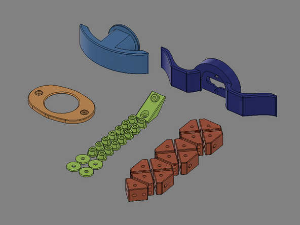
IMG 1 - Locate the Top Exit Panel, x1 Spacer Bar, the Top Seal Bar, x2 Precision Spacers, x6 TF Screws, x2 Brackets, one pair of Hinges and x4 Flange Washers. Some of these parts will be needed for Part 2.
-
IMG 2 - These parts will be stacked up in this order. Note the orientation of the Top Exit Panel during this step. It is upside down with the Exit Plugs (installed during Step 1) facing down.
-
There will be a small gap between the Top Exit Panel and the Spacer Bar. This space in needed for the next step.
-
IMG 3 - Verify the order of assembly. From the top down: Top Seal Bar, x2 Brackets, Spacer Bar, x2 Precision Spacers, Top Exit Panel and x2 TF Screws.
-
-
-
Do Not Use Power Tools for assembly.
-
NOTE: - These images will vary based upon the version being built, but will be assembled in the same way.
-
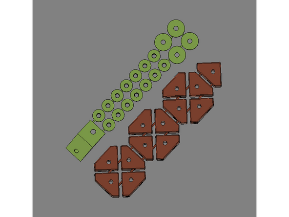
IMG 1 - The remaining parts from the previous step should be arranged as shown.
-
IMG 2 - Insert x2 Flange Washers into the Top Seal bar. Slide one Hinge into the gap and align its two outmost holes with the holes of the Flange Washers. Insert x2 TF Screws up though the holes in the Top Exit Panel and secure them into the Flange Washers. Repeat these steps for the other end of the assembly.
-
Do not fully tighten these four TF Screws. The Hinges need some free-float for a later step.
-
Note the Hinge orientation. The knuckles & pin must be facing down in this orientation. It is also advisable to insert the 'Hinge' leaf (with three knuckles) inward as shown.
-
IMG 3 - Repeat these steps for the other end of the assembly.
-
-
-
Do Not Use Power Tools for assembly.
-
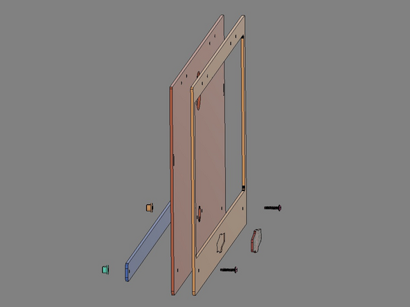
IMG 1 - Locate the Faceplate, Dome Label, Lid, Lid Brace, x2 TF Screws and x2 Flange Nuts.
-
To simplify the assembly, lay the Face Plate on a flat surface (with the engraved lines facing upward). Peel the protective backing from the Dome Label. Align the label with the engraved marks on the Face Plate (the label will cover all of these lines). Press the label firmly onto the Faceplate.
-
Lay the Lid on a flat surface and align the Face Plate on top of it. All holes should be in alignment. Insert the x2 TF Screws through the two lower holes (adjacent to the Dome Label). The screws should pass through the Face plate, Lid and continue on through the Lid Brace. Secure the screws with the x2 Flange Nuts.
-
BOWING THE LID: Please note, the hole alignment on the lid brace and the rest of the lid and faceplate assembly WILL NOT line up. This is INTENTIONAL to create a slight curve to the lid allowing it to seal properly in the bottom corners for PREMIUM kit owners with the seal gasket option.
-
IMG 2 - Verify that all components are aligned and secures as shown (front view).
-
IMG 3 - Verify that all components are aligned and secures as shown (back view).
-
-
-
Do Not Use Power Tools for assembly.
-
IMG 1 - Locate and align the Lid Trim Clamp, x2 TF Screws and x2 Flange Nuts. Insert the x2 TF Screws into the Lid Trim Clamp and through the Lid Assembly. Secure using the x2 Flange Nuts.
-
IMG 2 - Locate the Handle Front, Handle Rear and x2 TF Screws. Slide the Handle Front up into the Handle Rear and align the bottom faces. Insert the x2 TF Screws into the two resessed holes as shows.
-
IMG 3 - Locate x2 additional TF Screws. Align the Handle Assembly with the Lid Assembly (as shown) and secure together using the screws.
-
-
-
Do Not Use Power Tools for assembly.
-
NOTE: - These images will vary based upon the version being built, but will be assembled in the same way.
-
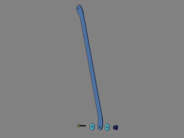
IMG 1 - Locate x1 TF Screw, x2 Precision Spacers, x1 Lid Prop and x1 Flange Washer.
-
IMG 2 - Align parts with the Main Assembly and secure them with the x1 TF Screw.
-
IMG 3 - Slowly tighten the x1 TF Screw. Make it just tight enough to allow the Lid Prop to move.
-
The Lid Prop can be mounted on either end of the RepBox to fit your preference. Addition Lid Props are available if a second one is more convenient.
-
-
-
Do Not Use Power Tools for assembly.
-
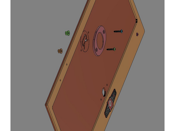
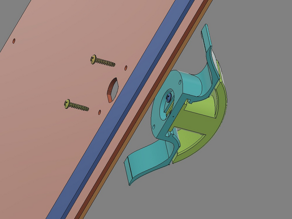
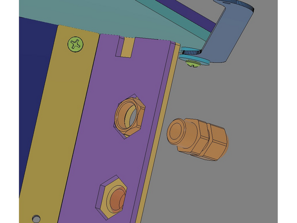
Leave the Front Cap attached to the Main Body of the fitting.
-
IMG 2 - Locate an open position on the Front Panel. Insert the Rear Nut into the corresponding hexagon recess. Align the Front Cap/Main Body with the opening in the Front Panel.
-
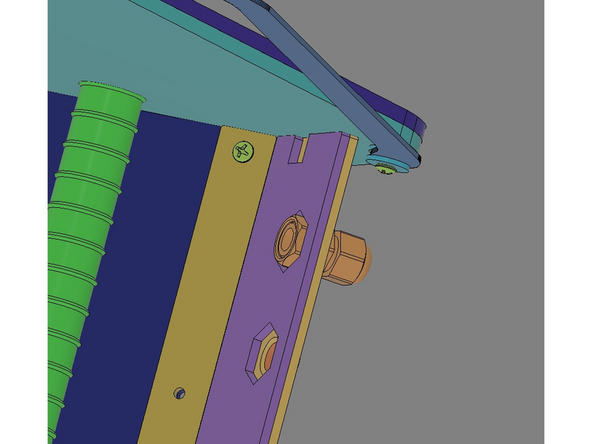
IMG 3 - The Front Cap/Main Body should pass through the Front Panel and screw into the Rear Nut finger tight (as shown).
-
-
-
Do Not Use Power Tools for assembly.
-
NOTE: - These images might vary based upon the version being built. The parts shown here are for v2.5.0. For v2.5.1 and V2.5.2, the parts will look different, but assembled in the same way.
-
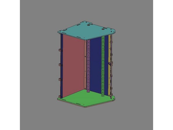
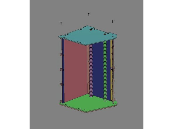
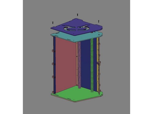
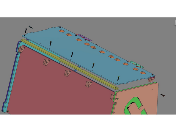
IMG 1 - Locate the Top Assembly, the Top Reinforcement Bar and x7 TF Screws.
-
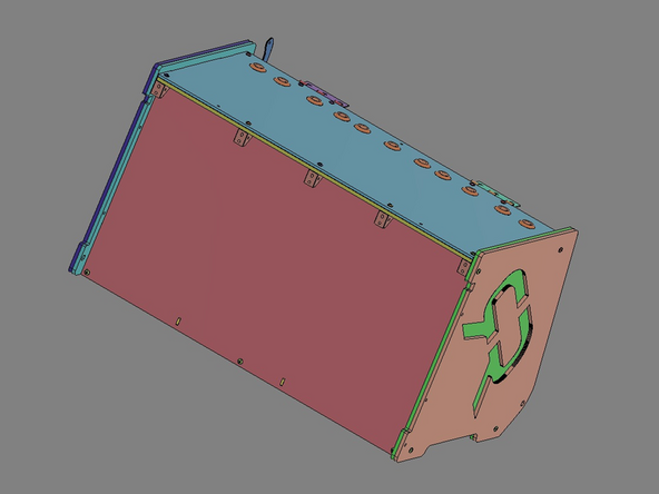
IMG 2 - Align the parts as show.
-
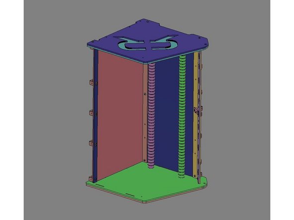
IMG 3 - Lower the Top Reinforcement Bar down onto the x5 Brackets. Then lower the Top Assembly down onto the Main Assembly and aligning all the screw holes.
-
The Top Assembly should fit into the alignment features of the Inner Side Panels. Do not force this step. You may need to loosen the screws on the sides to provide enough clearance.
-
Once aligned, insert the x7 TF Screws: x5 along the back rail, x1 in from the left side and x1 in from the right side. Secure the screws including the one screw left loose in Step 8.
-
-
-
Do Not Use Power Tools for assembly.
-
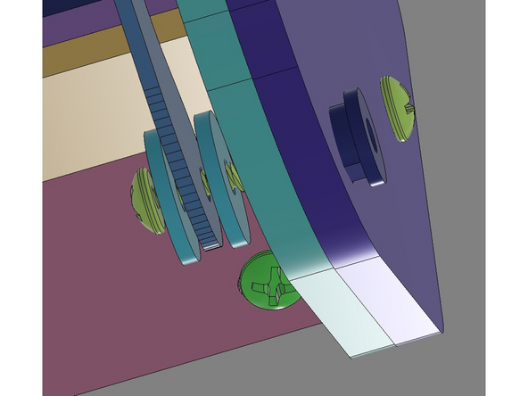
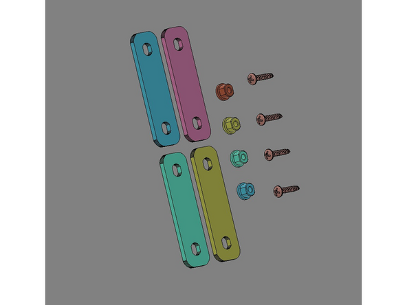
IMG 1 - Locate x4 Lid Clamps, x4 Flange Nuts and x4 TF Screws.
-
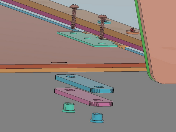
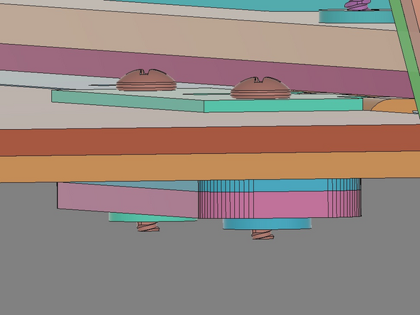
IMG 2 - Carefully flip the Main Assembly upside down. The x2 TF Screws will be installed from the inside of the box through the Hinges, then the Face Plate Assembly, continuing through x2 Lid Clamps into the x2 Flange Nuts as shown.
-
Do not fully tighten these screws. There needs to some free movement in this stack for the next step.
-
It can be helpful to insert the Flange Nuts into the outer Lid Clamps before stating this assembly.
-
IMG 3 - Verify the component stack before moving to the next step.
-
Repeat the process for the other Hinge.
-
-
-
Do Not Use Power Tools for assembly.
-
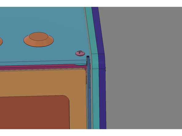
IMG 1 - The Hinges were left free to move in the previous steps to allow for their final alignment. Review the fit of the lid to define the adjustments necessary.
-
IMG 2 - The Lid Assembly will need to be move slightly to one side to provide clearance for the Lid Prop.
-
IMG 3 The Lid Assembly should lay evenly along the leading edge of the Front Panel.
-
The Outer and Inner Side Panels have been remove from this image to allow for better visibility of the Lid Assembly aligning with the Front Panel Assembly. You don't need to remove them for this step.
-
Slowly tighten all Hinge screws and make small adjustments until the lid is lined up correctly and is free to swing open/closed.
-
-
-
NOTE: - These images might vary based upon the version being built.
-
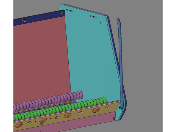
IMG 1 - Locate the x6 Seal Bars.
-
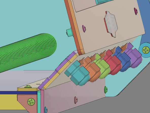
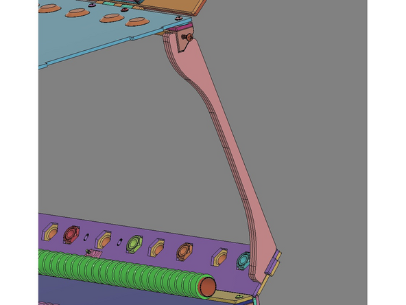
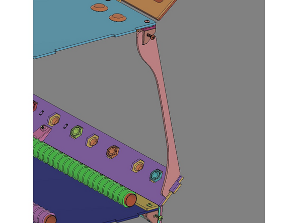
IMG 2 - Each Seal Bar can be installed as shown. The small alignment feature at the bottom of the Seal Bar will fit into a notch provided in the Front Panel Assembly. The feature at the top of the Seal Bar will fit around the Bracket.
-
IMG 3 - Add x2 more Seal Bars to this side (three in total).
-
The Outer and Inner Side Panels have been remove from these images to allow for better visibility. You don't need to remove them for this step.
-
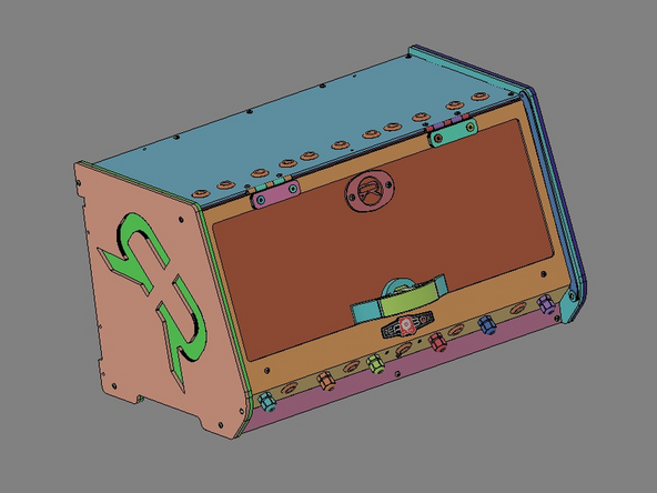
Repeat this process for the other side of the box.
-


Cancel: I did not complete this guide.
One other person completed this guide.

One Comment
Thanks for these instructions. As we have purchased the Prusa edition, we do have some parts left over with no instructions. We could figure out how to add the lock, also the gaskets are pretty obvious. What is missing is a hint that the lid - because of the bow introduced to it - will only close tight if the lock gets used (and only in lock position)...
We do have one piece of precision cut wood which definitely looks like it is a regular part of the assembly. It also fits inside nicely. But: It has five holes which have a larger bore on the broader side of the wood. There is also a small plastic bag with three very large screw-like wall plugs and three very long (!) brass screws. The wood, by itself, looks like it is intended as a wall mount for the assembled box, but I have no idea to what kind of wall these wall plugs are intended. If the wood gets fastened to a wall, this would definitely need some washers under the screws or the wood gets damaged. And what is the purpose of the larger bore?
Oliver Kluge - Resolved on Release Reply