
Introduction
This is the upgrade method we have employed on the Repkord print farm as it provides the best balance of speed and reliability when doing multiple machines at the same time. At this time we are confident this method will hold up well over time given our testing but if you are at all uncomfortable with this you may prefer to follow the standard METHOD 1 Outlined by E3D.
THIS IS A WIKI! As such it is a living breathing document. If there are details or images that you feel would better help illustrate how to do something please post them here to help others. Thank you to all those who have contributed!
-
-
Disassembly and removal of stock v6 hotend package per official E3D instruction steps 1-7.
-
Opening the wire bundle up by removing the cloth jacket all the way to the control box and exposing the full length of the heater and thermistor wires.
-
Mounting the REVO per official E3D instruction steps 15-21. Secure its wires with the provided Ty-wraps.
-
Cutting the provided E3D heater and thermistor *extension* wires to length and attaching the Splice Connectors.
-
Cutting the Prusa wiring for the thermistor and heater to line up with the E3D extension wires. Crimp these to extension wires using the Splice Connectors.
-
Replace the wire bundle wrap and zip tie it back to the hot-end.
-
Follow the final calibration steps outlined in the official E3D instructions for first layer and PID calibration.
-
-
-
Disassembly and removal of stock v6 hotend package per official E3D instruction steps 1-7.
-
Opening the wire bundle up by removing the cloth jacket all the way to the control box and exposing the full length of the heater and thermistor wires.
-
-
-
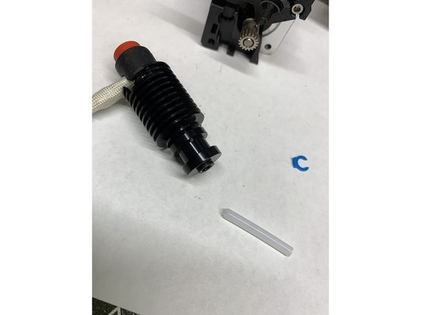
Insert the precut tube into the heatsink and secure with the clip provided.
-
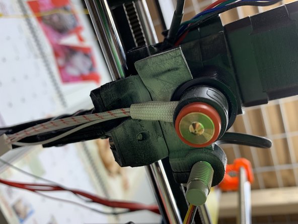
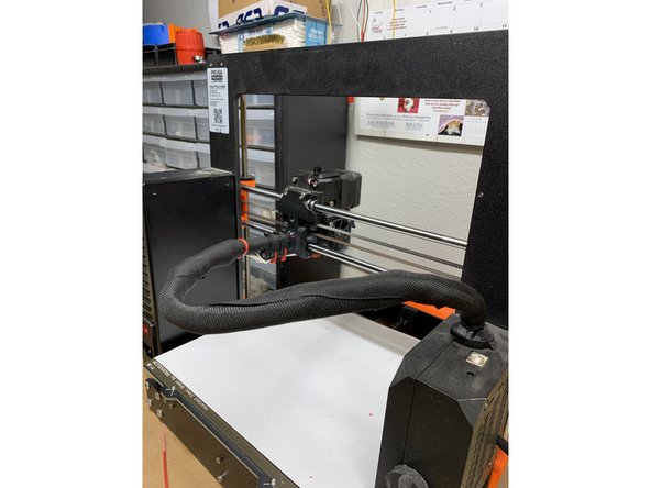
Install the Revo just as it was the original v6; align the wires through grove as shown.
-
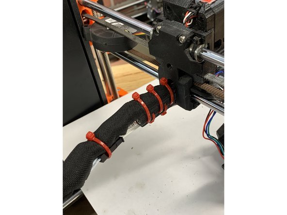
Secure these wires using the ty-wraps provided.
-
-
-
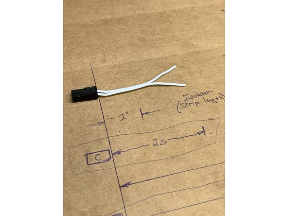
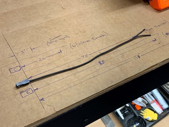
Cut the thermistor extension wires (white) as shown in Pic 1 to a length of 2.5 inches (~63mm) from the BACK of the Micro-fit 3.0 connector. This first length will ultimately position the Splice in the wire bundle closest to the hot-end.
-
Cut the heater extension wires (black) as shown in Pic 2 to a length of 8.5 inches (~216mm) from the BACK of the Micro-fit 3.0 connector. This second length will ultimately position in the Splice in the wire bundle closest to the control box.
-
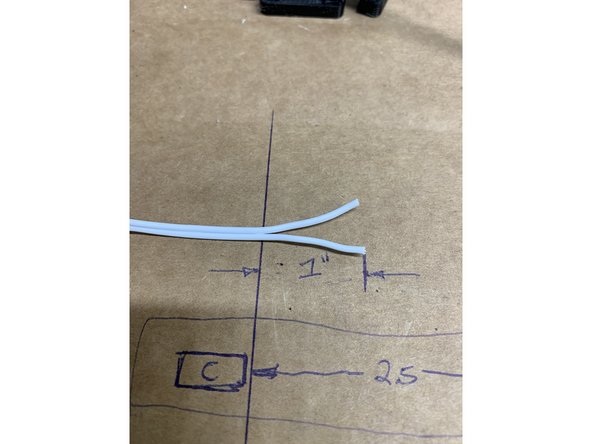
Separate the conductors one inch back from the cut (~25mm) of the two conductors from each of the cut ends (Pic 3). Do this to both extension cables.
-
-
-
These splice connectors require no special tools to engage and are designed to handle up to 5A of continuous current, more than enough for this particular application. Pliers can be very helpful to complete the crimping process.
-
These wires are NOT to be stripped prior to insertion in the splice connectors. The piercing of the insulation and its support are critical to the function and retention of the wires.
-
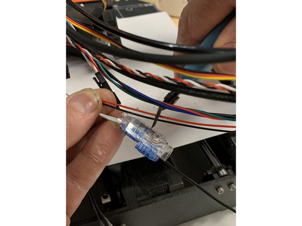
Position the wires of each end into the splice connector all the way into the body until they hit the endstop wall inside the connector (very close to the middle).
-
Squeeze one end of the splice down while watching as the wires are pressed into the knife edge conductors and continue to compress it until the blue button locks firmly in place. You'll notice the insulation and wire being curved in place to support the wire. This is by design.
-
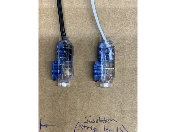
Insert the White pair fully into the crimp connector (one wire in each hole) to the middle of the housing and then squeeze to complete the crimp. The blue cap should stop completely flush with the clear body. Repeat with the black pair.
-
Connect these extension wires to the Revo tails using the Micro-fit 3.0 connectors.
-
-
-
The positioning of these splice connectors in the wire bundle has been carefully chosen to minimize the strain on the connections during 3D printing operations as well as the preventing excess thickness of the bundle in any given space.
-
In this installation we are retaining the quick connect Microfit 3.0 connectors for easy future removal and maintenance.
-
Before you cut any of the stock wiring its important that you cut and position the new extension cables provided with the kits to the lengths specified in step 4. These will dictate exactly where your splice connectors will go. They ARE NOT to be positioned directly next to one another.
-
-
-
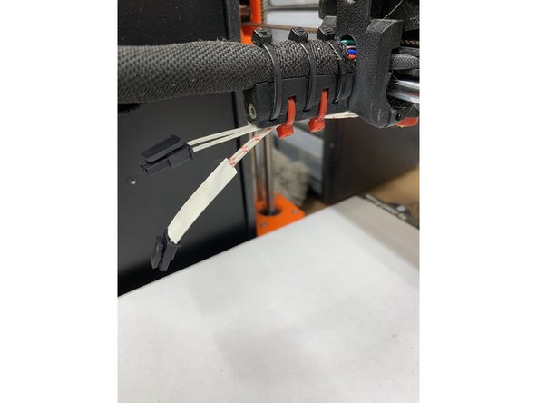
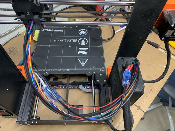
Loosely route the E3D extension wires along the main wire loom and cut the existing Prusa wires to length.
-
The Prusa thermistor Black & Red wires need no further prep once cut to length.
-
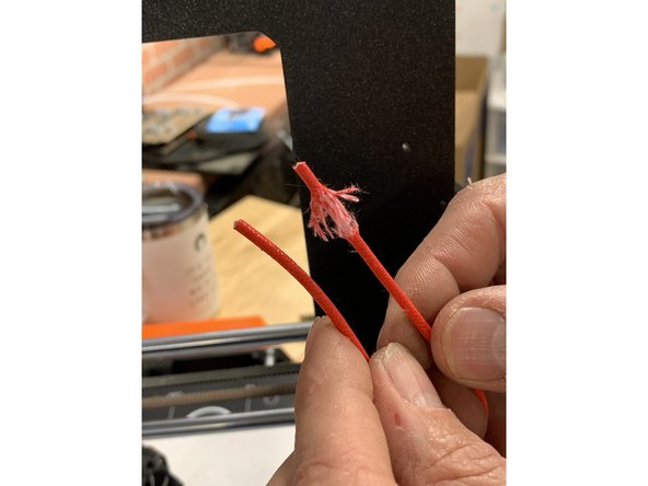
The stock heater cartridge wires have a red woven jacket over the the insulation that must be removed prior to use with this splice connector. You can easily do so with a razor or wire strippers. It is important that you DO NOT CUT/STRIP THE WHITE SILICONE INSULATION BENEATH the red woven jacket. REMOVE ONLY THE OUTERMOST woven JACKET.
-
Tip: try to un-weave the red fibers verses just pulling to strip.
-
-
-
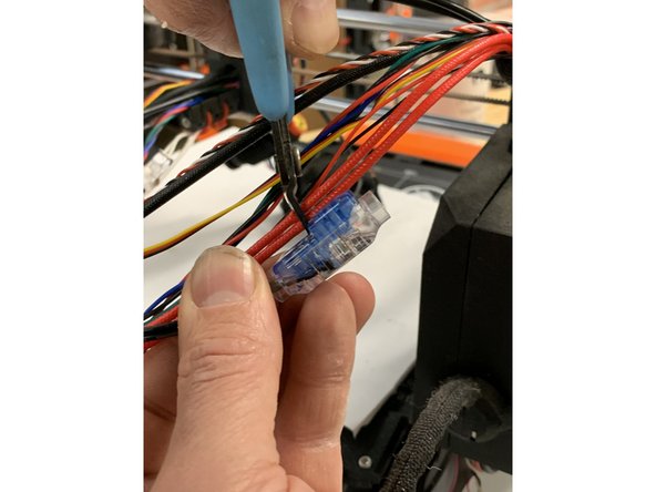
Fully insert the Prusa heater wires into the Black wire Splice (one wire in each hole) and squeeze firmly to crimp. Pliers might be required to fully seat the blue cap into the clear body.
-
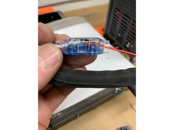
For the stock heater wire, again be sure that ONLY the red cloth jacket is stripped off and clear of the crimp. Only the white silicone jacket should be inside and compressed by the splice connector. Pic 1
-
Repeat the process with the Prusa Black & Red Wires into the White Splice.
-
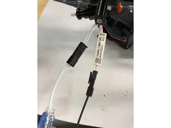
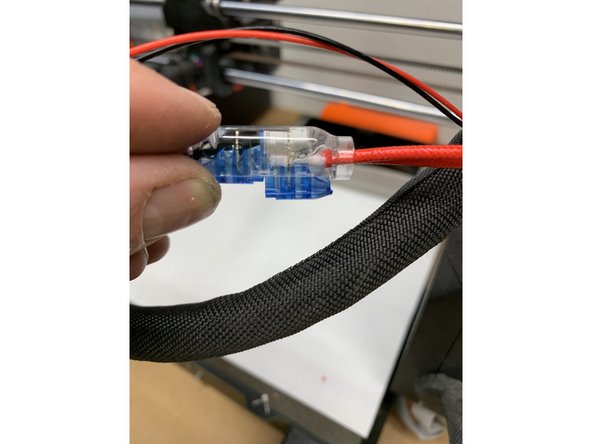
The crimps should be located as shown. If the wires are too tight/loose, the control box can be opened to adjust the final lengths.
-
-
-
Redress the wire loom into the wrap material and secure with ty-wraps. One additional ty-wrap should be used to secure the two Micro-fit 3.0 connector as shown,
-
-
-
Follow the final calibration steps outlined in the official E3D instructions for first layer and PID calibration.
-
HIGHLY RECOMMENDED: Some additional things to perform post install- Check your nozzle size setting in HW Setup menu if changed. Run the following Calibrations: Self Test, Full XYZ calibration, Temp Calibration, PID Calibration and finally run the First Layer Calibration.
-


Cancel: I did not complete this guide.
One other person completed this guide.
