-
-
Make sure the parts you have match up with what's listed on the bill of materials.
-
-
-
You will need the set of hex keys that came with your CR-30 or a similar set.
-
-
-
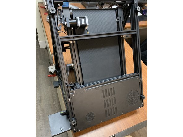
Tilt your CR30 up on end as pictured hanging the display and extruder off the side of a desk.
-
-
-
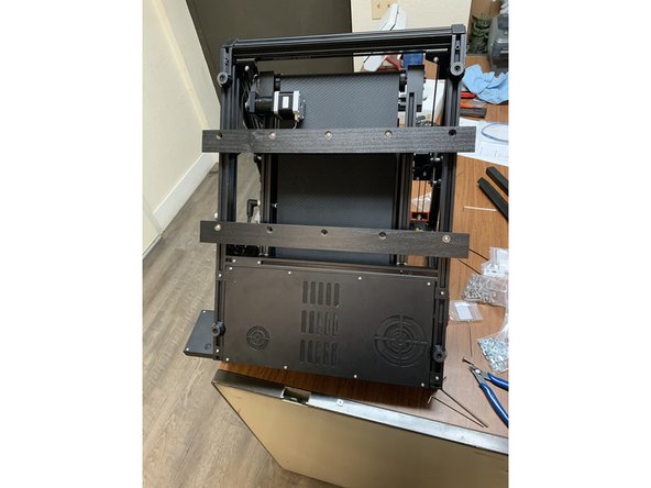
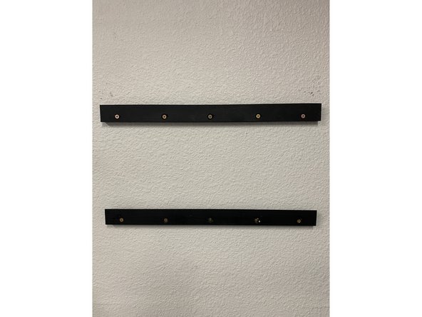
This is a quick look at the objective. You are attaching two french cleats to the underside of the CR30 frame and two to the wall.
-
Notice that the top cleat is fastened to the crossmember while the bottom cleat is only fastened to the side frame rails. This is intentional so that you can make fine adjustments to the cleat position if your wall mount ends happen to be off.
-
-
-
Start by laying your CR-30 on a table as pictured so the control panel and extruder / filament sensor are overhanging the side of the table. This will make it much easier to work on.
-
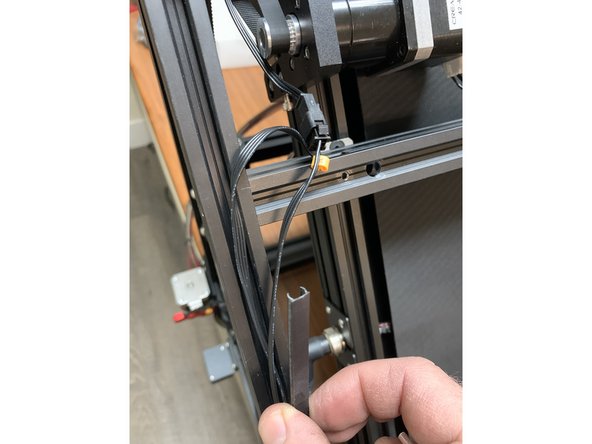
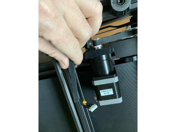
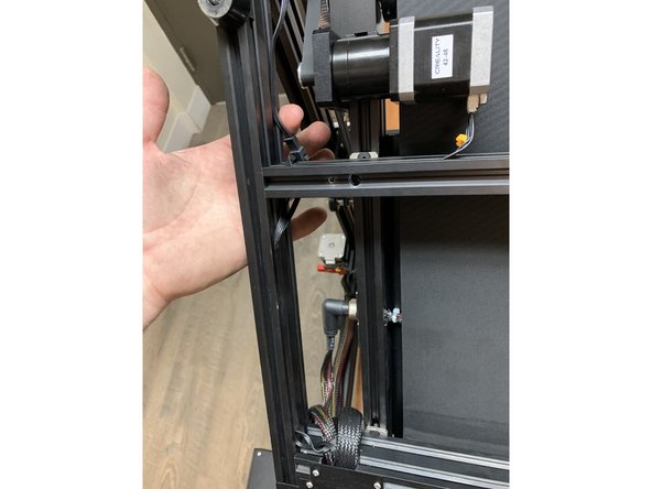
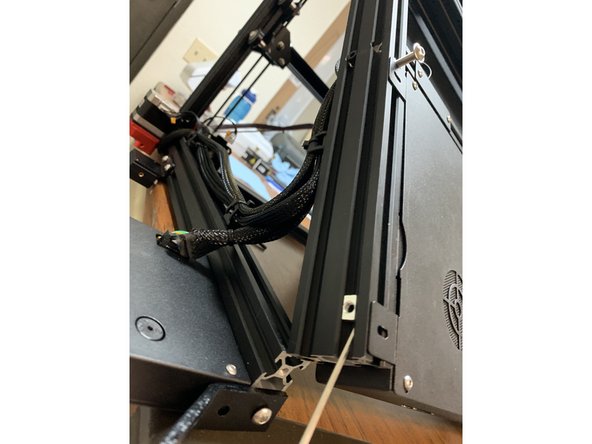
Start by re-routing the wiring for the Z-stepper and endstop from the bottom of the side frame extrusion to the side of it as shown.
-
When done correctly the bottom of the CR30 should be free of wiring to allow for the fasteners that hold the mounts.
-
-
-
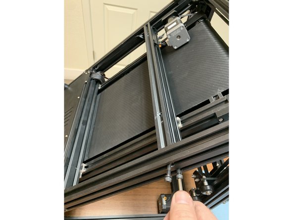
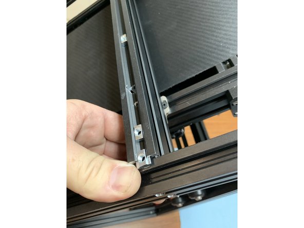
Your goal is to loosen the top beam beneath the belt just enough to slide three slide nuts in to the extrusion.
-
Start by removing the screws holding it to the side rail. You can do this on either side, the process is the same.
-
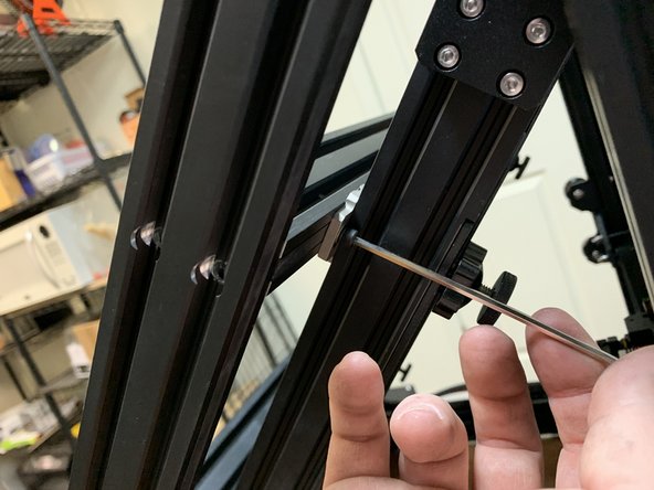
Loosen the screw holding the belt to the top of this crossmember. Doing so will allow you to flex this extrusion upwards enough to add the slide nuts to the extrusion. As shown in pic 3
-
-
-
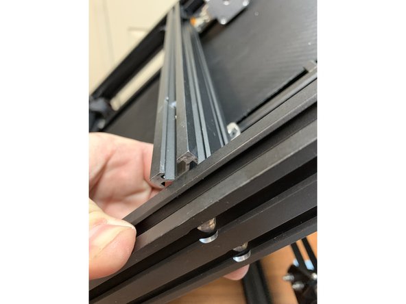
Insert 3 slide nuts into the top channel of the extrusion as shown.
-
Fasten the side bolts and the top bracket nut that you removed in earlier steps to free the extrusion.
-
You should now have the required connections for the top cleat. Lets move on to the base cleat and safety bracket.
-
-
-
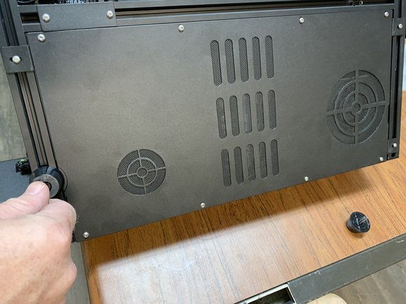
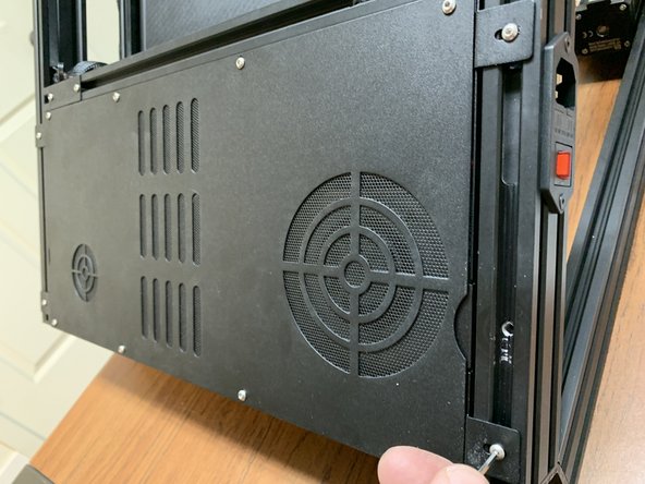
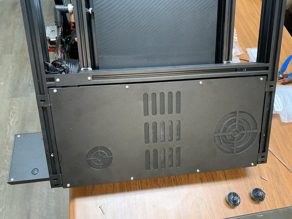
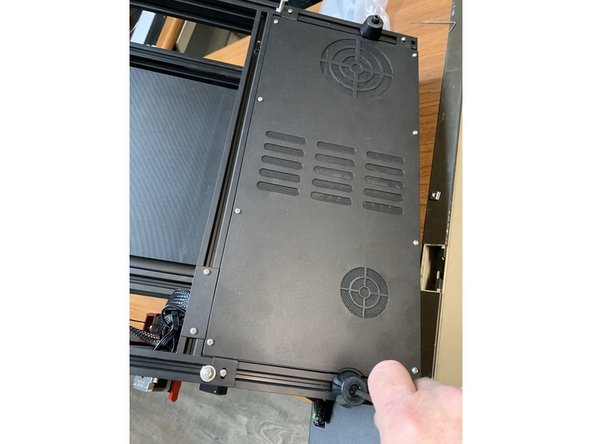
Remove the feet at the base of the unit by the electronics enclosure.
-
Remove the four screws holding the electronics tray to the frame.
-
-
-
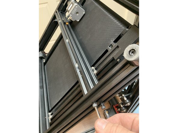
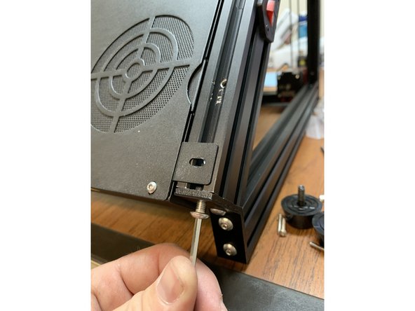
One at a time, remove the two screws holding the angled bracket to the end of the base extrusions.
-
Remove one of the remaining screws holding the angle bracket to the other extrusion so you can tip the angle bracket down and add a slide nut to the bottom side of the base side extrusions as shown.
-
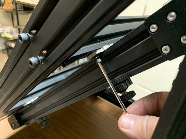
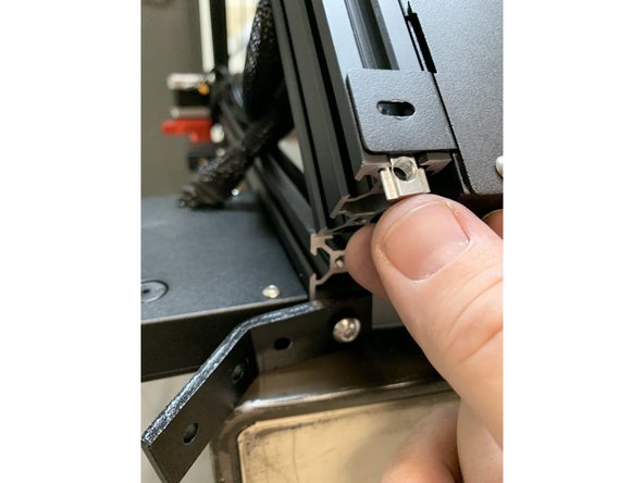
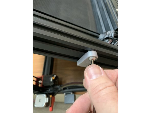
Using a hex key push the slide nut upwards in the extrusion as shown. If need be use a second hex key to hold it in place as you work it upwards in the extrusion past the electronics tray brackets.
-
-
-
Temporarily add a screw to hold the slide nuts in place above the electronics tray brackets as shown.
-
-
-
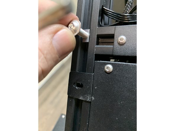
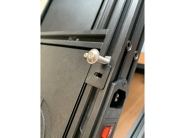
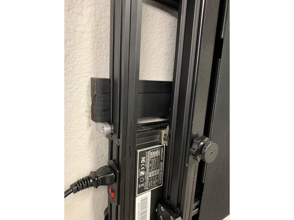
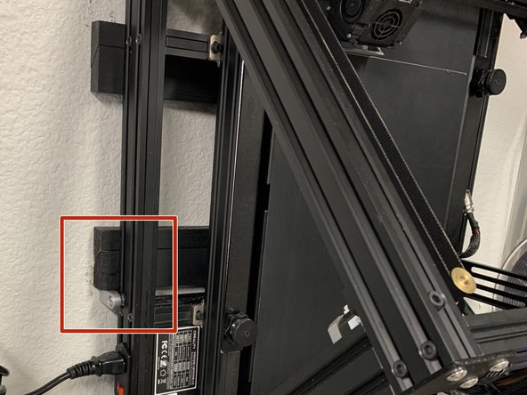
While the angle bracket is out of the way add another slide nut to the side of the extrusion closest to the display as shown. This is what the security bracket will connect to.
-
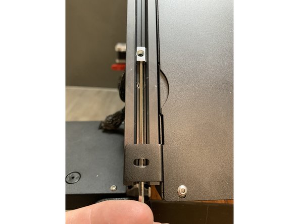
Temporarily remove the screw holding the lower crossmember beneath the belt to the side frame so we can slide the security bracket slide nut past.
-
Using one of the extra M5x12mm screws that came with your CR30 fasten the 3D printed safety bracket to the slide nut you just inserted. Leave it facing down for now so its out of the way. You can lock it in place later once its on the wall. Re fasten the crossmember screw you had to remove in the previous step.
-
-
-
Re attach the screws holding the electronics tray in place
-
Re fasten the angle brackets
-
Add the feet you removed back where they were.
-
-
-
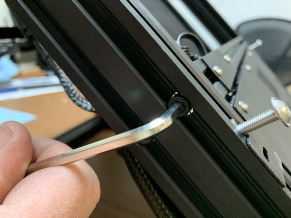
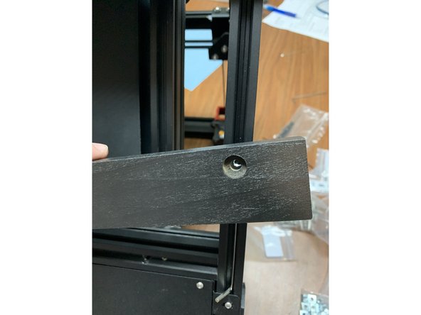
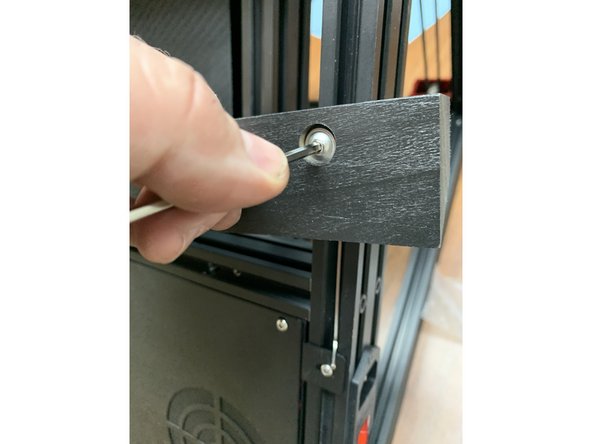
Use a hex key as shown to hold the slide nuts in the bottom of the side frame and line up the outer most cleat hole making sure the pointed end of the cleat is facing down.
-
Fasten the cleat to the slide nut using the provided M5x25mm pan head screws.
-
Repeat the process for both sides.
-
Make sure your cleat is perpendicular to the side rails so that the holes line up on the outer most edges of the cleat properly. If it is slightly off you will have a hard time getting the opposite side fastened.
-
Again, the base cleat is intended to be adjustable. When you hang it on the wall we will finalize the position it should be fastened into the side frame rails.
-
-
-
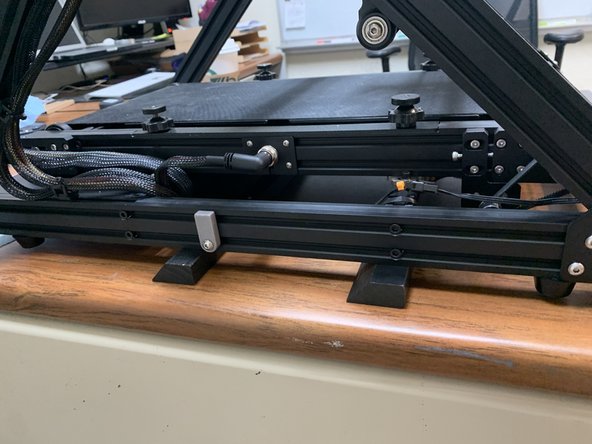
Notice how the CR30 lays firmly on the cleats when not wall mounted. This is intentional so you can easily remove it from the wall and print in its originally intended orientation without having to remove anything.
-
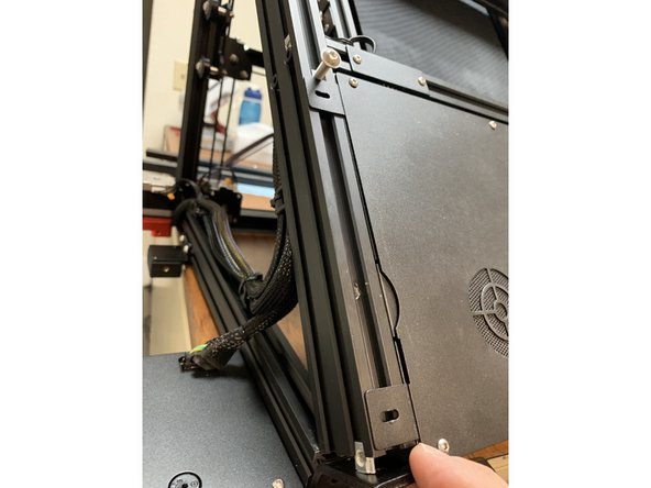
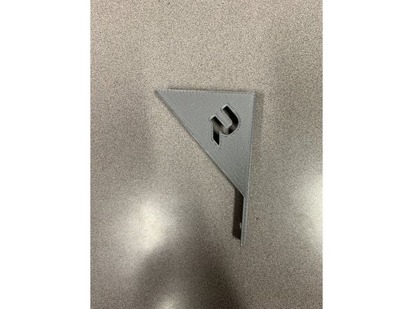
If desired we've included a 3D printed Screen angle adjustment. Simply remove the screws and T-nuts holding the existing control screen in place and mount the bracket to the frame.
-
-
-
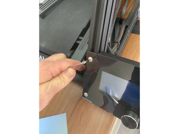
Start by removing the existing screws and T-Nuts from your screen mount.
-
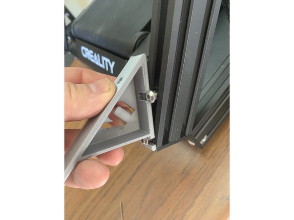
Re-place the t-nuts and screws in the track and line up the notched holes on your 3D printed bracket mount so it lines up with the screws and T-Nuts
-
Note: You may need to cut the zip ties holding the screen cable bundle in place in order for the wires to reach the screen with the mount angle adjustment installed.
-
There is also a 90 degree printable version of this mount available in our public file repository if you prefer to have the screen angled upward even more. This is handy in mounting situations when your printer is closer to the ground.
-
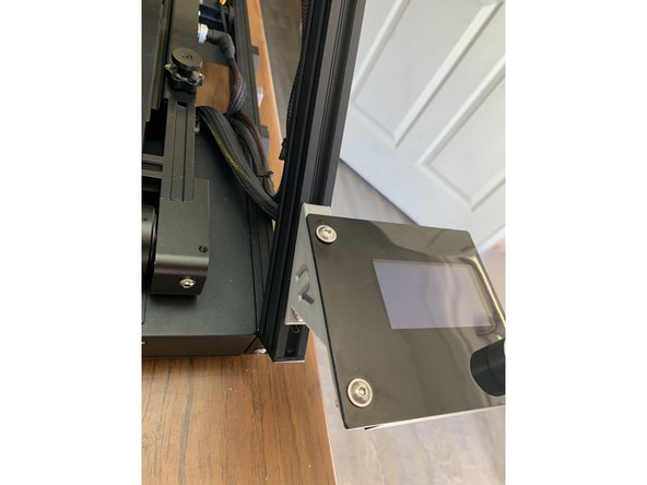
Fasten the screen back to the top holes of the 3D printed tilt mount using two M5x25mm screws.
-
Earlier versions of these mounts were designed so the screws would self tap as you thread them in. The current version in our public file repository has printable threaded holes.
-
-
-
WARNING: The CR30 is heavy. Improper mounting can be a safety hazard. If you are not comfortable checking that you have a secure installation please seek the help of a professional.
-
This is just a preview of what we're trying to achieve. Move through the following steps for more details on proper mounting.
-
-
-
We HIGHLY recommend mounting to as many studs as possible when mounting your CR30, however we realize this may not always be feasible for the location you select and we've included hardware for various wood framing and drywall mount configurations.
-
For metal framing or masonry configurations you will need to find anchoring hardware that's appropriate for that kind of installation.
-
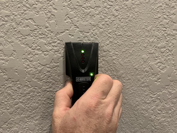
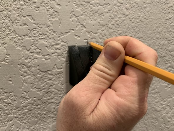
Start by marking your studs with a stud finder and a pencil.
-
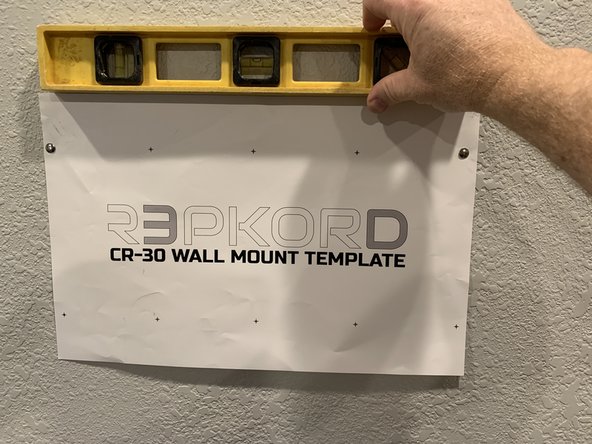
Use the mounting template and a thumbtack or needle to temporarily hold the template to the wall while you mark the other holes.
-
-
-
Press a tack through the top right hole of the template, ideally over the stud you marked and then using a level tack up the other side once you've verified that the top of your template is indeed level.
-
Use another pushpin or nail head or similar pointy object to punch through the mounting hole locations on the template.
-
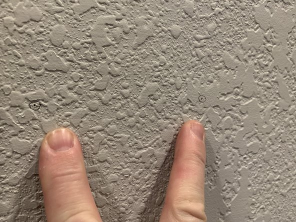
Once you've marked all the holes remove the template and circle your pinholes on the wall with a pencil for better visibility.
-
This is a good time to verify your stud positions once more before setting anchors and screws into your wall. If your stud spacing is standard 16" OC wood framed construction the holes at each end of the template and cleat should land directly on your studs for the most secure mount.
-
Even if you are only able to anchor to 1 stud that is still far better than using only sheetrock anchors. You may want to adjust the location of your holes so that the center of the cleat lands on your stud in a single stud mount configuration. Everyone's wall structure is different so its up to you to determine what is safest & most secure.
-
-
-
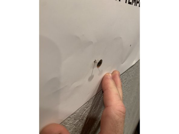
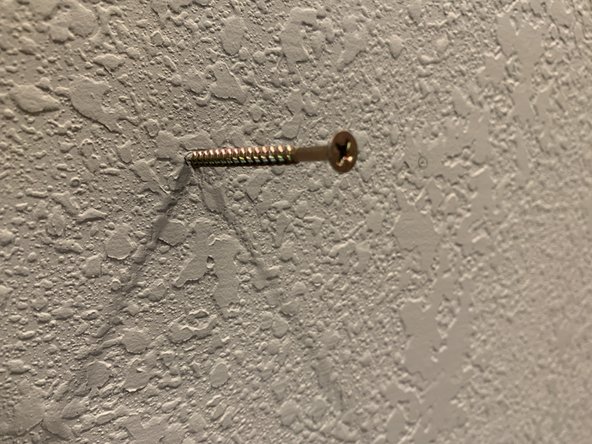
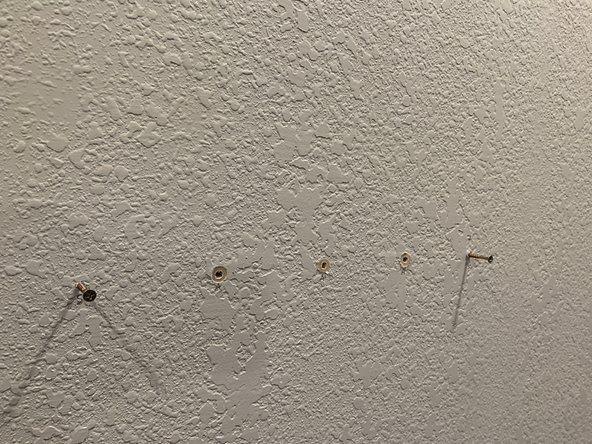
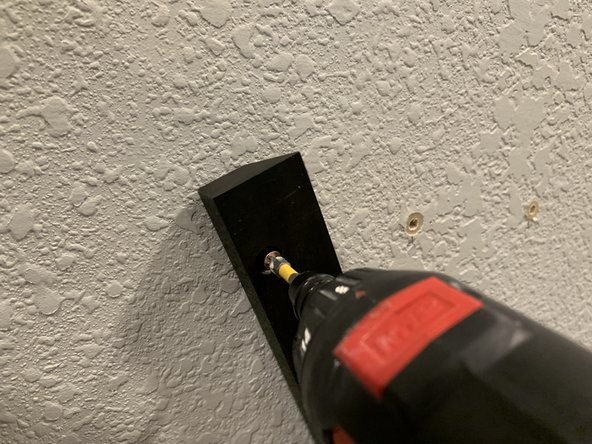
For the spots you're anchoring directly to a stud pre-fasten the gold screw to the stud using a screw gun to make sure you are making good contact with the stud. Mark this hole with an "S" to be clear this is a stud location when you do final mount.
-
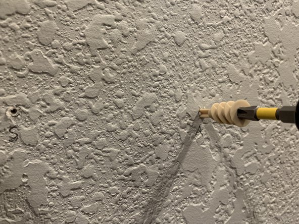
For the marked holes where there is no stud we'll want to set a drywall anchor. The best way to do that is to pre drill a hole slightly smaller than the anchor and slowly drive the anchor into the drywall using a Phillips or flat head screwdriver.
-
Set anchors and screws for each of the five mount holes as needed.
-
-
-
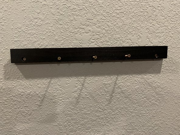
Start by hanging one end of the cleat into the marked hole so that the triangular top of the cleat is pointing straight up.
-
Tilt the cleat up and verify all your holes line up as marked and then set them in place.
-
Make sure your cleat is anchored securely to the wall before hanging anything from it. It shouldn't wiggle at all if mounted properly.
-
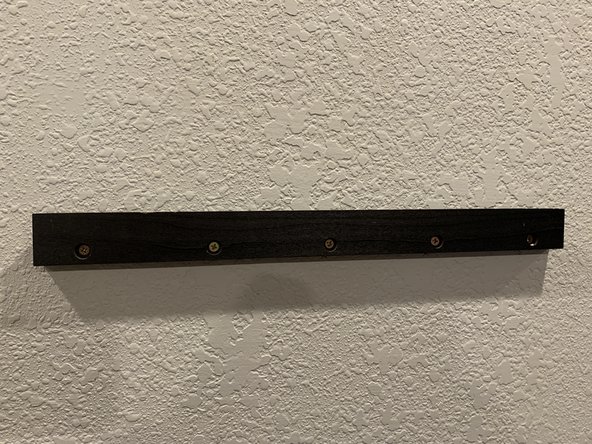
Once you're confident the top cleat is on repeat the same process for the bottom cleat that mounts just beneath it.
-
-
-
WARNING: The CR-30 is very heavy. Get help from someone else to lift and mount it on the wall. Use care to make sure everything is installed properly and that it cannot fall off the wall on to unsuspecting people or animals below.
-
Carefully place the printer on the wall by marrying the two cleat sides together.
-
Check the distance between your base cleat and the bottom wall cleat. If there is a gap between the cleats on the printer side and the wall side adjust the height of the base cleat in the side rails so that they marry perfectly as shown here.
-
Position your safety bracket and flip it around so that the CR30 can not pop off the cleats without removing the safety bracket. It should go underneath the bottom of the wall side cleat and rest snugly against it so the unit cannot be pulled off without removing the bracket.
-
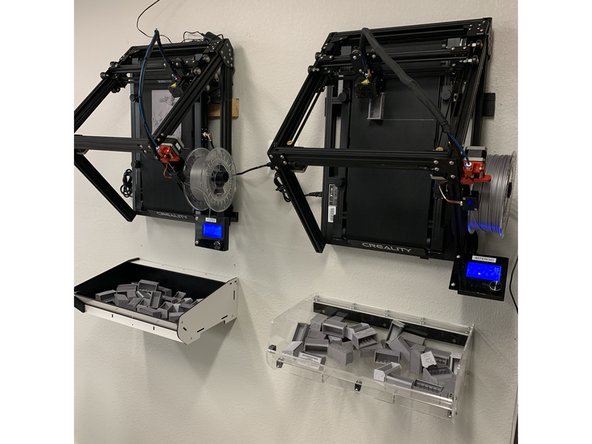
Plug in your CR30 and place a catch bin beneath to catch all the amazing new prints rolling off your new space saving wall printer!
-