
Parts
No parts specified.
-
-
Before you get started please be sure you've read and completed the pre-build guide which will go over all the parts that you should have and tools you'll need.
-
It may be handy to pull up the Parts Key PDFs attached to Stage 1 in a separate window or to print them out for faster reference.
-
-
-
The first thing you'll want to do is decide how you want the exit panels configured: With the holes facing towards the front or back or one of each direction
-
Your RepBox includes enough plugs to fill all the exit holes you decide not to use.
-
In the pictured configuration we've set the top panel to have them face front. But the panel can rotate 180 degrees and is interchangeable with the base panel.
-
Mosaic Pallette 2 Top Direct feed mode pictured. (Secondary Exit Panel Holes Top Front)
-
You may also want to consider this setup if you want to feed your wall mounted Mosaic Palette 2 from above: https://www.thingiverse.com/thing:329632...
-
-
-
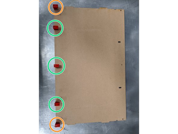
Grab one of the top / base panels (Part 4) and start by filling all its exit holes with plugs. This is much easier to do when its laying on a flat surface so better to do it now. You can always add or remove them later to install exit fittings as needed.
-
-
-
Flip your base panel over so the unfinished side is face up.
-
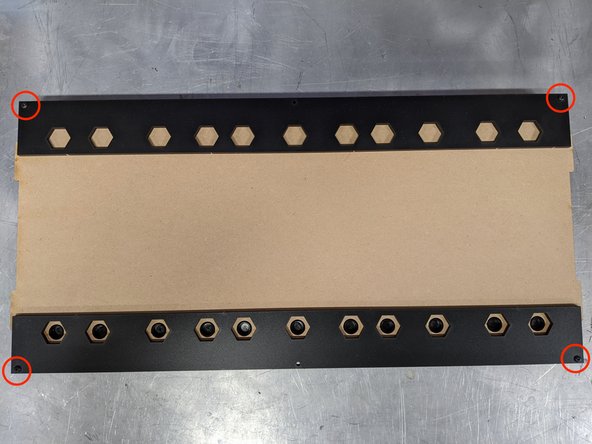
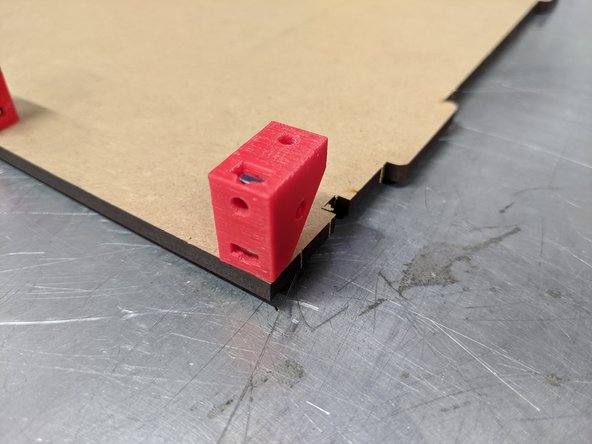
Grab both outside track guides (Part 2) and line up on either end so the 3mm holes at the edges line up with the ones on the base panel.
-
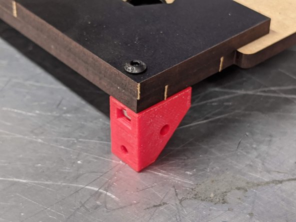
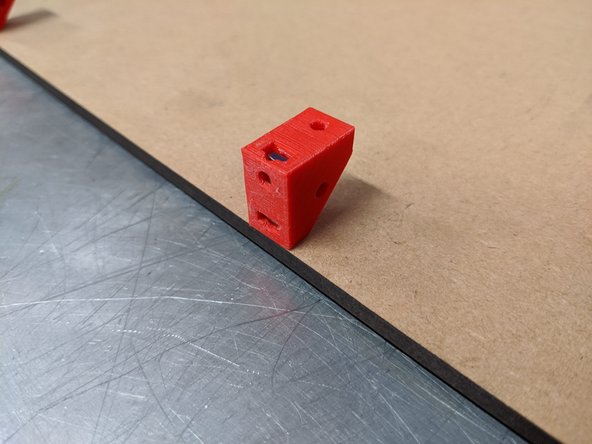
Affix the base corner brackets you prepped in Step 8 of Stage 1 Bracket Preparation as shown here. (link opens in new window)
-
You'll notice the holes at the corners are actually oval shaped. This is intentional and helps with sidepanel adjustment and minimizing gaps due to slight edge variance in the manufacturing process.
-
-
-
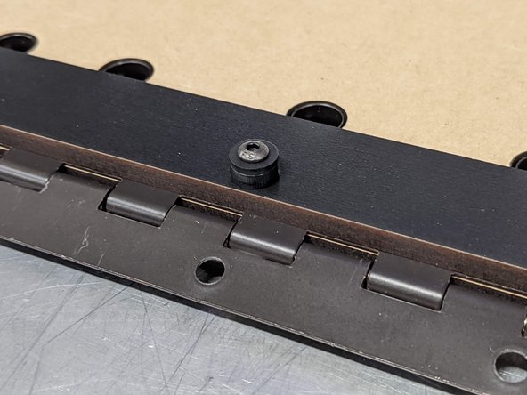
NOTE: The latest version of the box now uses a rectangular washer at the front center fastener point to help stabilize the adjacent exit panel. Please take a quick look at the next step for context of how this goes on the newest version of the box.
-
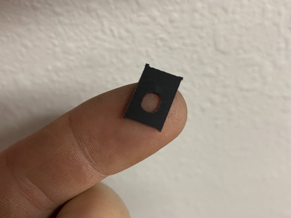
Grab a rectangular washer from the punch-out panel that has the roller sides in it (Part 7).
-
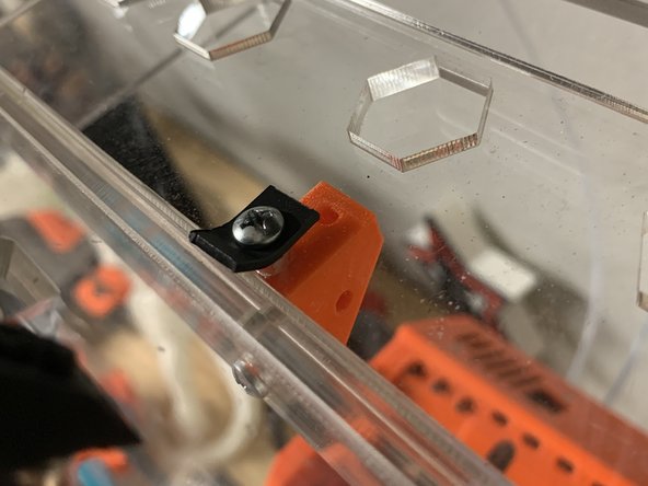
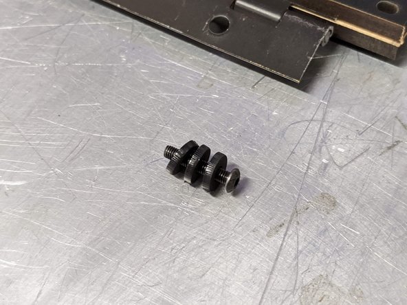
Press and M3x16mm screw through this washer. It will go on whichever side of the base you have decided will be the front of your RepBox. This is slightly different from what is pictured in the video as it was a late version change.
-
Affix the center base brackets you prepared in Step 10 of Stage 1 Bracket Preparation (link opens in new window) using the washered M3x16mm screws as shown here.
-
While seemingly trivial, the rectangular washer provides stability to the front exit panel and is highly recommended though not critical. See the next step for additional details.
-
-
-
This is the new rectangular washer referenced in the last step. It can be found as part of the Part 7 punch out sheet.
-
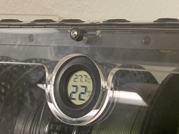
Pic 2 and 3 are two different angles of the front center bracket on the clear acrylic version of the box for clear context of proper installation
-
The screw you have in your kit may look different depending on what version of the RepBox you have received.
-
-
-
Locate the back panel (Part 1)
-
Affix the top rear corner brackets prepared in Stage 1 Bracket Preparation: Step 12 as shown here. (link opens in new window)
-
-
-
Affix the top rear center brackets you prepped in Stage 1 Bracket Preparation to the back panel (Part 1) as shown here. (link opens in new window)
-
-
-
DECISION POINT: Choose what side you want your base exit holes to be positioned at (front or rear) before fastening the rear panel. They are most commonly located to the rear of the box to feed down along a wall to your 3D printer. This of course can be changed later on if desired.
-
The configuration shown here has the exit holes to the rear (plugged holes closest to the rear panel)
-
Connect the rear panel to the base assembly as shown here.
-
-
-
Press two rivnuts downward through the finished side of the inside exit panel (Part 9)
-
Lay the inside exit panel with the installed rivnuts finished side down so the rivnuts are sticking up through the unfinished side.
-
Line up the top edge of the inside and outside exit panels and then press the outside exit panel (Part 10) over the protruding rivnuts. The finished side of the outside exit panel should be facing up.
-
Fasten the two pieces together using two M3x16 screws. If assembled correctly only the finished sides of each panel should be exposed.
-
Set this assembly aside for use in later steps.
-
-
-
Grab your remaining top / bottom exit panel (Part 4). Its time to configure the top panel.
-
Start by filling all the exit holes with plugs. You can remove them later to install exit fittings as needed.
-
While not required to do at this step you'll find it easier to press in the plugs now while the panel can lay flat against your work surface.
-
-
-
CRITICAL STEP: READ CAREFULLY
-
The finish on the continuous hinge can sometimes make the hinge holes too tight for the rivnut to fit into and needs to be scraped away.
-
The material is very soft and can be easily reamed out using needle nose pliers, a phillips head screwdriver, or even the side of the hex key that comes with the hardware kit.
-
Simply run any metal tool inside each of the holes until you can fit a rivnut in each one. NOTE: Not all holes are used but its generally easiest to just ream all of them out now so the ones that are used are properly prepared.
-
-
-
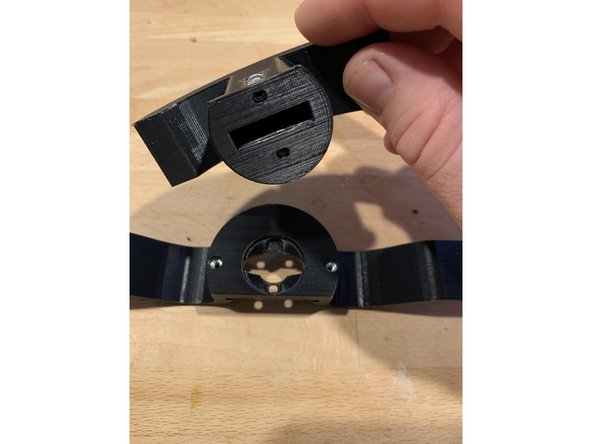
CRITICAL STEP: Watch / Read Carefully
-
It is CRITICAL to the proper sealing and alignment of your Repbox that your hinge be oriented correctly. Be sure that the hinge pin (rounded side) is installed so that it is on the OUTSIDE of the RepBox when completed (Face Down towards the table as shown here).
-
Decide which side of the top panel you want your exit points to be located. In this example we're locating them in the front but the panel is symmetrical so you can just as easily have them exit from the rear. Configure as desired. You may of course disassemble and reconfigure in the future if desired.
-
Press three rivnuts into the top panel and flip the panel over as shown in the video here. The excess tip of the rivnut should be sticking up through the unfinished side of the panel.
-
Orient the continuous hinge (Part G) so the hinge pin is facing down and then press it over top of the exposed rivnut tips. The fit will be tight, this is intentional so that the lid stays as square to the box as possible.
-
Press the top hinge clamp (Part 5) over top the hinge with the finished side facing up as shown here
-
If the hinge isn't pressing on easily make sure your rivnuts are pressed all the way through the top panel and are perfectly vertical. You may also need to check that you reamed the hinge holes out as indicated in the previous step.
-
-
-
CRITICAL STEP READ CAREFULLY
-
It is CRITICAL to the proper sealing and alignment of your Repbox that your hinge be oriented correctly. Be sure that the hinge pin (rounded side) is installed so that it is on the OUTSIDE of the RepBox when completed (Face Down towards the table as shown here).
-
Prepare three M3x16 screws with the styrene washers (Part 6: Punchouts)
-
Fasten the hinge clamp (Part 5) with the washered screws inserted into the rivnuts protruding from the top panel as shown in the video.
-
-
-
CRITICAL STEP: WATCH/READ CAREFULLY
-
Grab two rivnuts and one M3x16 screw from the hardware bag (Parts Pack E)
-
Press the rivnuts through the ends of the lid brace (Part 14) so that the excess is sticking out on the unfinished side of the brace.
-
Grab your acrylic lid (Part 16) and be sure all the masking has been removed from it as indicated in the preparation stage.
-
Lay the front faceplate (Part 15) on top of the acrylic lid so that the hole patterns line up and the curved corners are closest to you.
-
Attach only one side of the lid brace to the faceplate/lid assembly with an M3x16 screw. Leave the screw slightly loose. This will aid in completing the next step.
-
-
-
CRITICAL STEP: WATCH/READ CAREFULLY
-
Bowing the lid helps ensure that the lower corners maintain a good seal when used with the optional seal kit.
-
The goal is to bend the lid so the brace acts like the string of a bow holding the lid in tension and creating a slight arc as shown in the video.
-
Start by only partially fastening an M3x16mm screw to the unfastened rivnut. You will need to angle the screw and rivnut slightly to get it started. DO NOT TIGHTEN MORE THAN A FEW TURNS AT THIS POINT.
-
Be careful not to cross-thread your screw and rivnut here. If it's not going in smoothly, stop and re-seat the screw in the rivnut.
-
Slowly and gently bow the faceplate/lid until you are able to press the unseated rivnut into the hole in the acrylic panel. Hold it in place with your fingers and then tighten the screw the rest of the way.
-
Take your time and watch the video carefully to see the process.
-
-
-
CRITICAL STEPS: READ CAREFULLY
-
Align the top panel with the hinge clamped on so its facing you as shown in the video.
-
Press four rivnuts into the hinge holes that line up with the holes on the top edge of the lid assembly.
-
If the rivnuts aren't pressing into the hinge please be sure you reamed any excess hinge coating from the holes as instructed in earlier steps.
-
-
-
Optional: After punching out the lid clamps (Part 17) you may want to color the breakaway parts using a sharpie as shown here.
-
-
-
If you have ordered the optional humidity hunter kit this is a good time to remove the circular knock-outs in the faceplate and lid to later accept the hygrometer.
-
To minimize the chance of damaging the faceplate or lid we recommend scoring the tabs at the four extents of the circular knock outs with a hobby knife or snip away at them lightly with flush cutters. Doing so will minimize the risk of cracks when knocking out the discs
-
Place the lid and faceplate on the edge of a table and with the blunt edge of a screwdriver or small hammer repeatedly rap on the disc until it pops free of the part. You're better off striking it a few times repeatedly than overly trying to smash through... especially on the acrylic.
-
-
-
CRITICAL STEP. READ/WATCH CAREFULLY!
-
The lid clamps (Part 17) ensure that your screws don't protrude too far through the rivnuts holding the lid to the hinge. If you don't use them your lid will not be able to close fully.
-
Carefully bend the hinge 90 degrees so the top panel / lid assembly can stand up on its own. Make sure the rivnuts stay pressed into the acrylic of the lid as they are still unfastened.
-
Place one M3x16mm screw through the end of one of the lid clamps so the button head is on the finished side of the clamp and fasten to the topmost rivnut from the outside of the lid assembly as shown here.
-
Fasten the other side of the lid clamp with another M3x16mm screw.
-
Repeat the process for the lid clamp at the bottom side of the hinge.
-
PLEASE NOTE: On the latest shipping version your faceplate and lid will have a center hole in it also. Fill this hole with an additional rivnut and screw with 3 of the flat washers installed on it so that the screw seats at proper height. We will update the imagery to coincide shortly. SEE THE REFERENCE PHOTO ON THE NEXT STEP FOR CONTEXT
-
-
-
As mentioned in the previous step, newer boxes may have a center hole in your lid and faceplate directly above the "R" Circle or where your Optional Hygrometer may go. This is normal and you fasten it using the same technique as outlined in the previous video for the lid clamps.
-
Use an M3x16mm screw and place three (3) styrene washers Part 6 from the punch out sheet (Part 7) and fasten through the hinge and holes with a rivnut as outlined for the lid clamps.
-
You may need to scratch off a small amount of powder coating from the hinge as outlined in the last step in order for the rivnut to press through.
-
-
-
Before you fasten the top corner brackets to the top panel you'll want to grab one of the thin RECTANGULAR washers from the punch out sheet on your roller panels (Part 6: Shared with rollers sheet - Part 7) SEE THE NEXT STEP FOR PHOTO DETAILS OF THE UPDATED RECTANGULAR WASHER
-
Notice the slight gap left at the ends of the top panel and hinge clamp. Carefully slide the thin RECTANGULAR washer into the gap so that it lines up with the holes for the top panel and hinge clamp.
-
If the washer falls too far into the gap you can easily slide it out by using one of the roller panels (Part 7) to dig it free.
-
Fasten the top corner bracket you prepared in Stage 1 Bracket Preparation (link opens in new window) to the top panel with an M3x16mm screw as shown here.
-
Take notice of the bracket's orientation and make sure it matches what you see in the video
-
-
-
This is a photo of the Rectangular Washer from the updated part 7 punch out sheet. It is provided here for better context from the previous step as the video has yet to be updated with this new part.
-
This is the same new washer referenced in Step 5. Only 3 are currently in use on the newest version of RepBox. You may have extra on your sheet. This is normal.
-
-
-
Repeat the process from the last step for the front right corner bracket.
-
Insert a thin RECTANGULAR washer in the end gap between the top panel and the lid clamp so that it lines up with their holes.
-
The RECTANGULAR washer is a recent update and is not shown in this video at the moment. You may have an older version that uses a standard washer here instead. Either will do the job just fine.
-
Fasten the top corner bracket you prepared in Stage 1 Bracket Preparation (link opens in new window) to the top panel with an M3x16mm screw as shown here.
-
Take notice of the bracket's orientation and make sure it matches what you see in the video
-
-
-
If you do not have the optional seal kit skip to Standard Handle Install
-
Insert the latch core (Part 22) into the hole for it on the acrylic lid so that the key side is facing your work surface.
-
If the metal latch bar is attached you'll need to remove it first.
-
Place a single key into the latch core as shown
-
Fasten the latch core to the acrylic lid with the latch core nut.
-
With the key in the vertical position attach the metal latch bar to the latch core with the provided screw and a phillips head screwdriver. Make sure the cutout in the latch bar is facing you and aligned as shown in the video.
-
Verify the operation of the latch with the key in it and then return it to the open position.
-
-
-
Place two M3 Square nuts into the nut traps on either side of the 3D Printed Handle Set (Part 20) as shown. Verify that the top handle is broken free from the bottom handle by trimming any tabs left over from the 3D printing process with flush cutters or a hobby knife.
-
The top handle should be able to rotate freely in the channel of the base handle as shown in the video.
-
-
-
If you received your RepBox after July 1st 2020 You may have received the revised design that uses Rivnuts instead of square nuts. While functionally the same we've found it to be slightly easier to align and fasten while reducing the risk of stripping the screws.
-
To fasten simply place two Rivnuts on either side of the handle and press into place as shown.
-
The latest version of this handle set is available for download with the rest of the printed parts.
-
-
-
The handle set has also been updated to more easily attach the top and base handle pieces back together in case you separated them and do not have the latch kit installed.
-
By default the handle will come as one piece for those who don't have the latching option (included with the seal kit)
-
-
-
Rotate the latch so its in the closed position and the key is aligned horizontally along the acrylic.
-
Place the handle set on top of the key so that it slides into the handle set as shown.
-
Using two M3x16mm screws CAREFULLY fasten the handle set to the acrylic lid. It is very easy to accidentally cross thread these screws here If you meet any resistance STOP and back the screw out. Verify that the holes and threads of the screw are free of debris and try again.
-
Do not overtighten the screws or you may crack the acrylic.
-
-
-
If you ordered your RepBox after July 2020 you may have the updated latch handle that uses Rivnuts instead of square nuts. This is normal. Please see the notes on the updated handle set here.
-
NOTE: If you did not order the optional seal kit then the hole for the latch set will not be used and will simply be covered by the handle set.
-
Place two M3 square nuts into the nut traps on the sides of your 3D printed handle set (Part 20)
-
Verify that you are EASILY able to thread an M3x16 screw into each of the square nuts once they're in the handle set. If you meet any resistance STOP and clear any holes and/or screw threads from debris and try again.
-
It can be easy to accidentally cross-thread the fasteners in this step. Take your time and make sure everything screws together easily. It should not require much force to thread these screws.
-
Place the handle underneath the lid as shown and fasten it using two M3x16mm screws.
-
Do not over-tighten the screws or you may crack the acrylic.
-
-
-
Here's where it all starts to come together! Start by placing your left sidepanel (Part 8) with the printed side down against your work surface.
-
Insert the tabs of the base/rear panel assembly into the corresponding notches in your sidepanel.
-
Insert the tab of the center track guide (Part 3) into the corresponding notch of the sidepanel as shown. Its ok to gently leave it hanging away from the base for now.
-
Insert the tab of the front exit panel assembly from step 9 into the corresponding notch of the side panel as shown.
-
Place the left sidepanel onto the tabs of all the parts / assemblies you just placed. Go slowly, its easiest starting with the rear tabs, then make sure the center track guide is flat against the base panel and seat its tab along with the base. Lastly verify the front exit panel is seated in its notches.
-
Once you've verified that the sidepanel is on all tabs, fasten only the bottom two brackets using M3x16mm screws.
-
Slowly slide your hand under the right sidepanel and hold it tightly in place so you can turn it over without the tabs from the center panels falling out.
-
Once you've turned the box over fasten ONLY THE BOTTOM TWO brackets to the left sidepanel with two M3x16mm screws as shown.
-
-
-
If you don't have the optional seal kit (Pack I) skip to Attaching The Top Panel / Lid Assembly
-
Place two M3 Square nuts into the tracks of the 3D printed latch plate (Part 21)
-
Fasten the latch plate to the inside of the front exit panel assembly with two M3x16mm screws as shown.
-
Align the front edge of the latch plate with the front edge of the inside exit panel to start. You may adjust it later to suit your latching tension preference.
-
-
-
NOTE: RepBoxes shipped after July 2020 provide extra styrene washers included with the roller panel sheet instead of the wooden ones for securing the top lid to the rear brackets. This is normal and will not affect performance.
-
Almost there! Place the tabs of the top panel / front lid assembly into the notches in each of the side-panels as shown.
-
Prepare three M3x16mm screws with the styrene washers (Part 6)
-
Fasten the top panel to the top rear center brackets using the washered screws you just prepared.
-
Fasten the top panel to the top rear corner brackets using two M3x16mm screws as shown.
-
-
-
Turn the RepBox on its side and using two M3x16mm screws SLOWLY fasten the sidepanel to the top front and rear corner brackets. If you meet any resistance STOP and back the screw out to check for debris in the threads and/or holes, then try again.
-
These screws can accidentally cross thread if you don't align them properly to start. None of the fasteners in this assembly should require much force to thread.
-
Flip the box over and do the same thing on the other side.
-
-
-
Remember the oval holes seen at the corners where the brackets attach to the side panels? Nows the time to use them.
-
If not already loose, loosen the corner brackets for the top front, top rear, and base front and rear brackets where they fasten to the top, rear, and base panels.
-
Press the sidepanels tightly against each corner and then re-tighten the loosened screws.
-
The goal is to minimize any joints between the sidepanels and center body panels.
-
It may not be possible to completely remove the gaps due to slight variance in manufacture. If you're concerned about air incursion we recommend using a silicone to seal the joints on the outside of the box where its easiest to apply.
-
Silicone is the preferred sealant since it can be readily removed should you want to reconfigure your box in the future. Small squeeze tubes that don't require a caluking gun can typically be found at your local hardware store for less than $5.
-
-
-
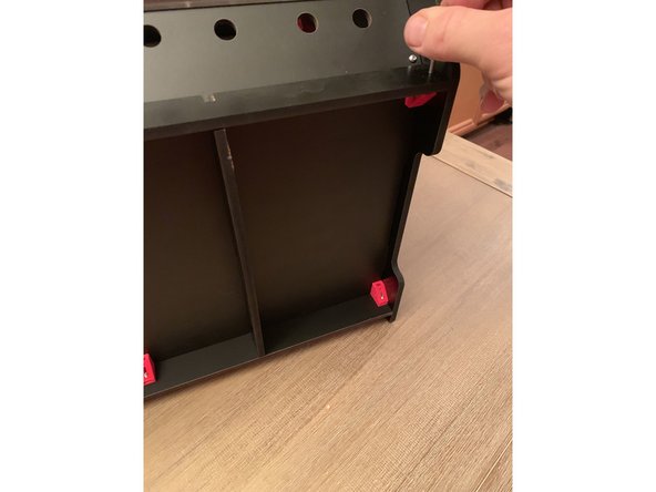
The plinth provides extra reinforcement to the base when loaded with filament.
-
Place the tabs of the two base stringers (Part 12) into their corresponding notches on the rear panel.
-
Place the stringer support bar (Part 11) over top the brackets at the front of the base carefully lining up the tabs of the base stringers with the notches in the stringer support bar. DO NOT FASTEN WITH SCREWS YET
-
Place the base faceplate (Part 13) on top of the stringer support bar so the finished side is facing outward and the holes align with the stringer support bar when their bottom edges are aligned.
-
The base faceplate is taller than the stringer support bar because its designed to fit in the channel formed by the front exit panel and keep it form pressing outward.
-
Fasten the base faceplate and stringer support bar to the front three base brackets using three M3x16mm screws as shown.
-
-
-
NOTE: RepBoxes delivered after July 2020 include an optional M3 Nylock for fastening your lid prop more securely to the box.
-
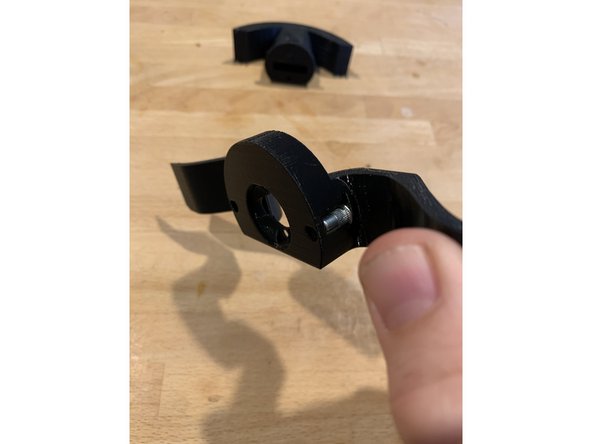
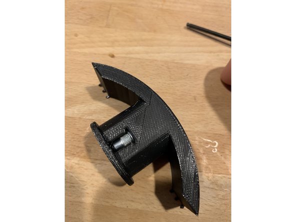
The lid prop holds your lid open while you load and unload your RepBox similar to the way your the hood of your car may be propped open.
-
You may fasten your prop to either side of your RepBox. We are showing it done on the right side here but its the same process for the left.
-
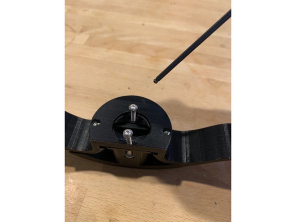
Press a M3x16mm screw through the outside of your side panel to form a fastening post.
-
Slide a thin washer (Part 6) over top the screw as shown.
-
Slide on the lid prop so that the curve of the prop follows the contour of the sidepanels.
-
Add one more thin washer and then fasten using a rivnut with the flanged end tightened against the thin washer as shown.
-
You may adjust the tension of the lid prop by holding the rivnut with your fingers and then tightening the screw on the outside of your RepBox
-
-
-
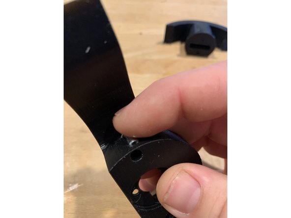
To prop your lid open simply lift the lid, pull out the lid prop, and place it in one of the notches of the acrylic.
-
There are two notches on each side of the inside of your lid for the lid prop to rest in. You will generally want to use the notch closer to the hinge so that the lid stays more open.
-
The farther notch allows the prop to only be opened as high as the top panel when being used with the under shelving suspension kit.
-
-
-
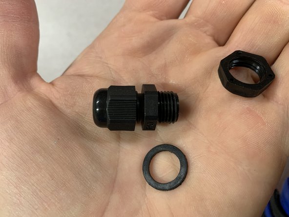
Due to slight variances from suppliers your exit fittings may look slightly different from those pictured. This is perfectly normal and they will still function the same.
-
The fittings you receive may or may not have rubber washers installed when you receive them. These washers are not necessary for the functioning of the RepBox and WILL LIKELY INTERFERE WITH ALLOWING YOU TO THREAD THE FITTING INTO THE NUT UPON INSTALLATION
-
In the event that your exit fittings do not grip the nut in the next step verify that you have removed the rubber washer and then flip the nut over in the hexagonal nut trap of the exit panel and try again.
-
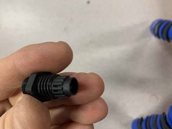
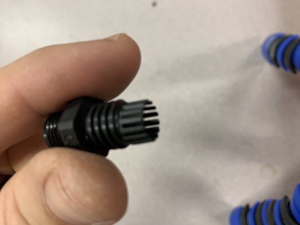
Pic 2 and 3 show the internal compression mechanism of the exit fitting with its cap removed. You'll notice a series of small "teeth" that should have a tall rubber gasket installed between them as shown in Pic 2. As the cap is tightened it compresses this gasket around any optional PTFE tubing you may have installed.
-
You may need to twist the cap completely to get a firm grip on any optional PTFE tubing you may be using. If its not gripping make sure the gasket is indeed installed and you may always add pieces of tape to the outside of the PTFE tube to increase compression/grip.
-
-
-
Pick where you would like to place your exit fittings based on spool size and printer positioning. Remove any plugs from the holes that you want to exit filament from.
-
Remove the nylon nut from your exit fittings. IF THERE IS A RUBBER WASHER WITH YOUR EXIT FITTINGS REMOVE AND DISCARD THEM
-
Place the nylon nut in the trap on the backside of the front or base exit panels and thread in the fitting from the other side of the hole.
-
For the top panel exits there is no nut trap. Simply hold the nut with one hand while threading the fitting in with the other.
-
Replace any unused holes with exit plugs to minimize air incursion into your RepBox.
-
EXIT FITTING USAGE NOTE: The exit fittings have a small gasket in them that compresses when you tighten the cap on it. When using in conjunction with narrower diameter PTFE tubes you may need to tighten rather firmly to get the gasket to grip. If your tubing still slips, use some tape around the tube to add friction at the gasket point.
-
Exit fittings are compatible with 1.75mm and 3mm diameter filament.
-
-
-
Congrats! You've made it through the main assembly. No small feat. Maybe enjoy a life saver or two from your Mini RepSaver box if you haven't eaten them all already ;)
-
When you're ready its time to move on to Stage 3: Roller Assembly ->
-
-


Cancel: I did not complete this guide.
5 other people completed this guide.

10 Comments
The box is solid so far, great job and great design! I agree the videos are too fast and rather frustrating when trying to orient the brackets correctly in the beginning. Overall assembly went together okay minus a couple brackets that were installed the wrong way (video showed bracket mostly hidden in the installer’s hand), and other things that held me up. Step 13 frustrated me with the lack of washers needed. I used 3 for each m3 screw and seems okay to me now.
I can still recommend this box to others, but its not a quick project.
Wes Cooper - Resolved on Release Reply
Just finished this build. I really like the product, but the instructional videos are really frustrating. Pictures would be so much better. Thanks
Carl Clore - Resolved on Release Reply
Continued…
I noticed that on the bottom angled plate for the exit fittings that the screw heads went into the plate slightly so I used the spare set of thick washers to support it. Not sure if I missed something here, but I would think you would want washers for those screws since the heads are close to the drilled holes on the plate.
Also when I put in the humidity sensor, it wouldn’t fit through the front hole in the door so I had to unscrew the door plate at the top to slip it in. I would suggest that those with a humidity sensor put that in when assembling the front door.
All in all, I at least got everything together on the main portion of assembly and it looks great.
I again want to thank you for a great product and looking forward to more accessories in the future.
Regards,
Paul Butler
downeastaa - Resolved on Release Reply
Thanks Pooch and team for a great product.
But… the instuctions were very difficult to follow and really needs supporting documentation (like diagrams, charts etc). I didn’t have the ability to look at a screen while I assembled so it took me close to 4 hours to put together (just the main assembly).
One thing that would be very helpful - since the videos are very limited, is put a diagram next to the video to at least show exactly what you need - number of screws, which panels, washers, and finished assembly etc - otherwise you try to follow the video and read the description and it is a big challenge especially when it came to the brackets since there are like 4 or 5 different combinations. Of course without prevail the little square nuts would fall out on some of them and then I had to guess what we needed for that stage. The difficulty being moderate is an understatement - well at least with the directions supplied.
Regards,
Paul Butler
downeastaa - Resolved on Release Reply