
-
-
Base Panel Assembly
-
Left and Right Side Panel Assemblies (Seal Kit Side Panels will look different from pictures)
-
Top Panel Assembly
-
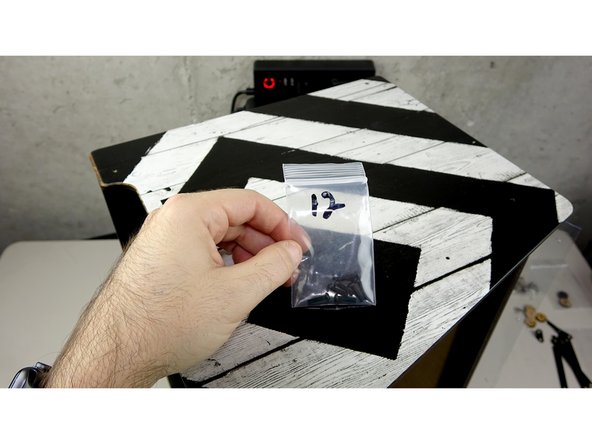
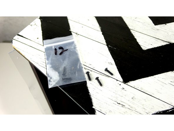
12mm Bolts, 20mm Bolts
-
Nylock nuts
-
Wall Mount Cleat (the one with the holes on the tips of the end)
-
1.5" Lath Screws (Silver), 3/4" Lath Screws (Black)
-
Graphic Side Panels (not pictured)
-
-
-
Take the Top Panel Assembly and attach it to the Base assembly Back panel as pictured. (The seal kit version will NOT have the brackets attached to the top panel yet.)
-
If you have difficulty getting the tabs into the slots, you can use a pair of needle nose pliers to tapper the tab. Don't over do it. Playing with the tabs TOO much can actually make the wood expand and make it harder.
-
Carefully start inserting the tabs of the top , back, and base panels into their corresponding holes.
-
-
-
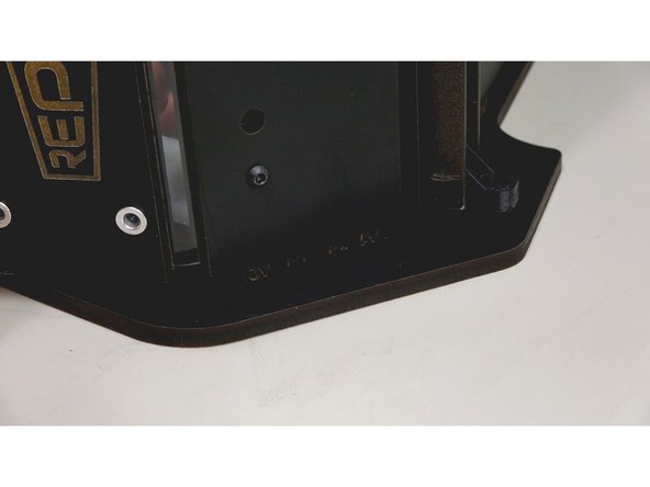
Carefully bend the front exit plate panel up to insert into the tab holes. Your nylock nuts should still be semi loose to aid in the poisoning.
-
If you have not done so yet, insert a nylock into the L bracket that is seated against the side panel.
-
SEAL KIT ONLY: Use a 20mm bolt to secure the 3D Printed Trapezoidal Corner Bracket on the side panel to the top panel. You should have an open holes on the ends of the top panel towards the front. The 20mm bolt will pass through the top panel, the vinyl, the clamp panel, and go down in to the bracket, catching on the square nut.
-
-
-
Carefully Flip over the assembly to where the attached side panel is up.
-
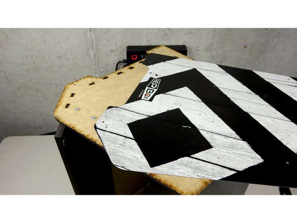
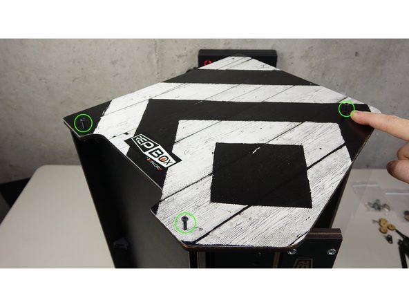
Find the correct graphic face plate that fits over the panel and place it on top of the side panel.
-
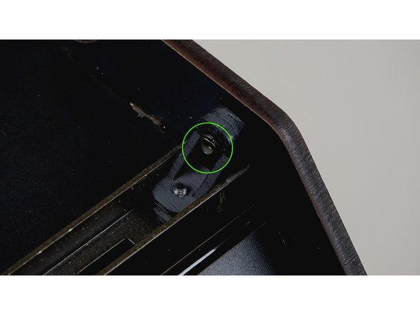
Using 12mm bolts, secure the Graphic face plate and side panel to the rest of the assembly. (mount points circled in green in 3rd pic)
-
If your bolts don't catch on anything when securing the bottom portion of the side, make sure there are nylock nuts in the angle brackets and L brackets on the bottom of the base panel.
-
-
-
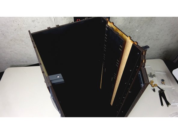
Insert the Center Track Guide panel into the tab holes of the mounted side panel.
-
Tip the assembly over onto the side panel that is mounted.
-
Carefully align and press the other side panel into place, making sure to catch the tabs of the Center Track Guide and Front Exit plate.
-
Once all tabs are in their corresponding holes, take the other Graphic side panel and place it on top of the unsecured side panel.
-
Secure the panels into place using 12mm bolts as you did on the other side panel.
-
You can now tighten down all of the Nylock nuts on the front panels!
-
SEAL KIT ONLY: Use a 20mm bolt to secure the 3D Printed Trapezoidal Corner Bracket on the side panel to the top panel. You should have an open holes on the ends of the top panel towards the front. The 20mm bolt will pass through the top panel, the vinyl, the clamp panel, and go down in to the bracket, catching on the square nut.
-
-
-
THIS IS A MANDATORY STEP! Even though this is part of the Wall Mounting system, this is important to install to ensure the stability and rigidity of the unit as a whole.
-
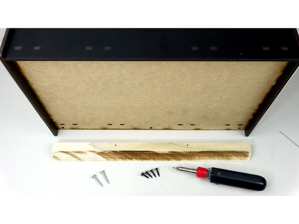
The Wood Support Beam (aka: French Cleat) with holes in the ends.
-
1.5" Silver Wood Screws (2)
-
3/4" Black Wood Screws (4)
-
Phillips Head Screwdriver
-
-
-
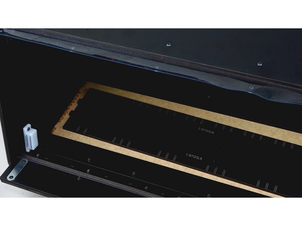
Make sure the wood beam you have is the one with the holes drilled on the ends. There are two beams, and only one of them has the holes on the ends.
-
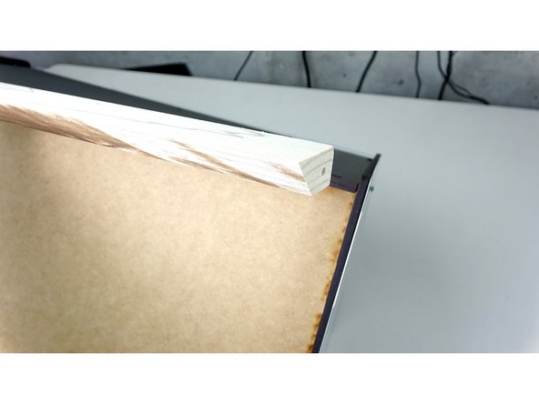
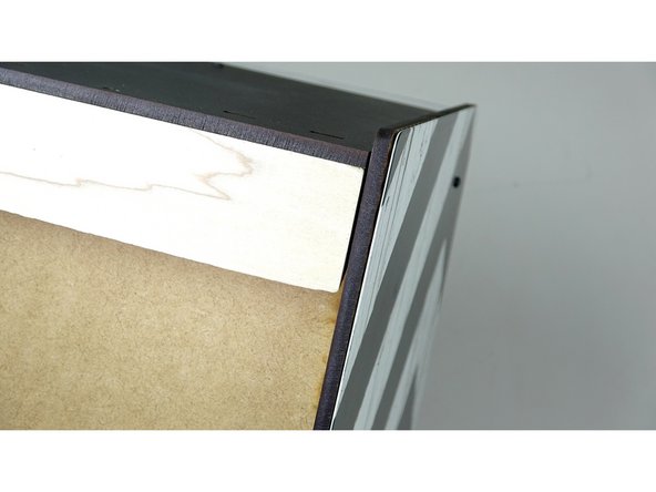
Insert the beam flat against the back panel, in between the two side panels. The angled part of the wood piece should be facing inward and down.
-
You'll need your Phillips head screwdriver for the next couple of parts
-
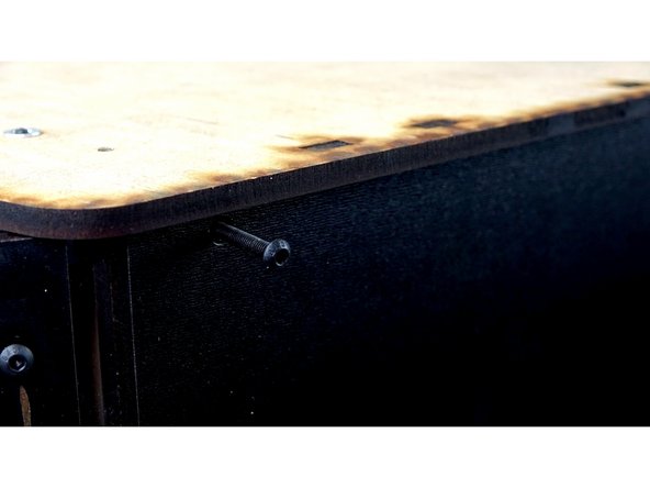
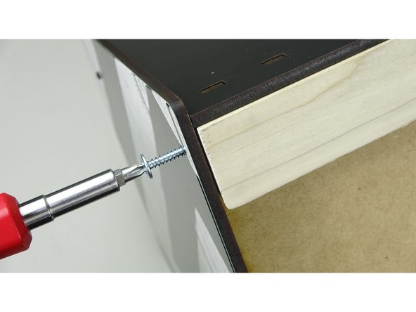
Start securing the wood beam into place by using the 1.5" Silver Wood screws (one on each side). These should pass through the graphic panel, side panel, and screw into the hole at the end of the wood beam.
-
-
-
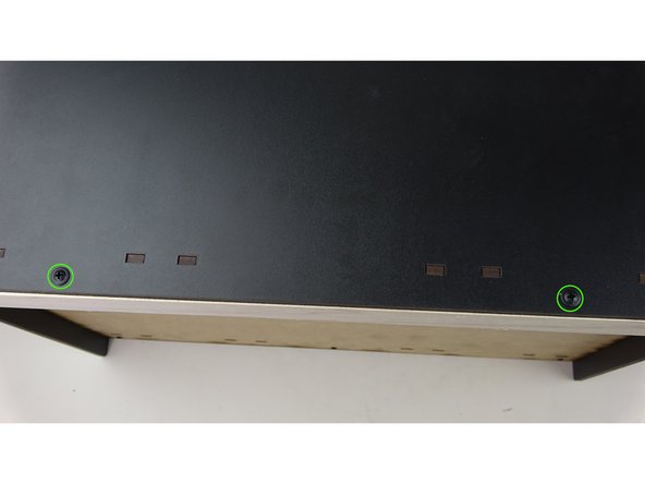
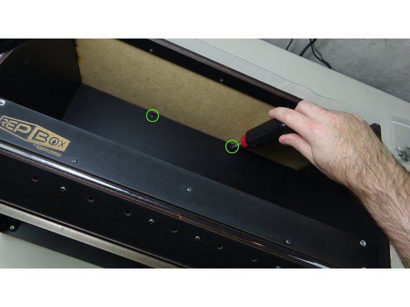
Finish securing the beam into place using the 3/4" Black Wood screws.
-
Two will go through the top panel into the beam.
-
Two will go through the back panel into the beam.
-
-


Cancel: I did not complete this guide.
One other person completed this guide.
