
-
-
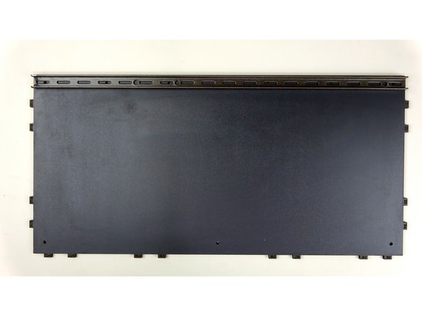
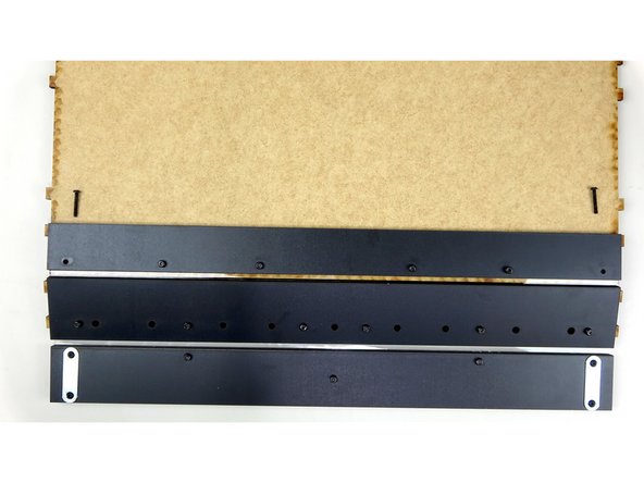
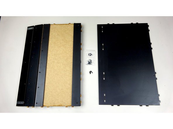
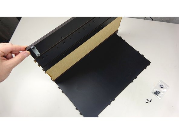
Finished STAGE 1 Face Assembly
-
16mm bolts, 20mm bolts (found in the bracket bag), Nylock Nuts, Square Nuts
-
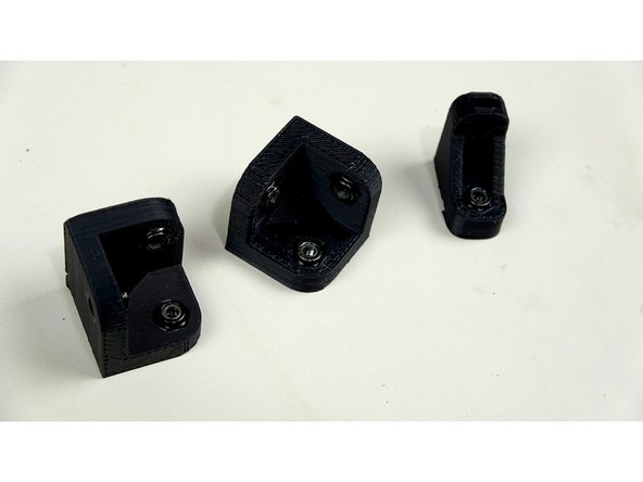
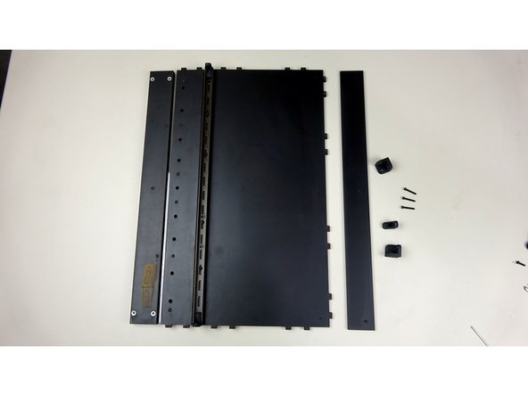
3D Printed brackets
-
Front Track Guide Panel
-
Steel Base Support Beam
-
Base Panel
-
Not Pictured but used later: Rear Track Guide Panel, 12mm bolts
-
-
-
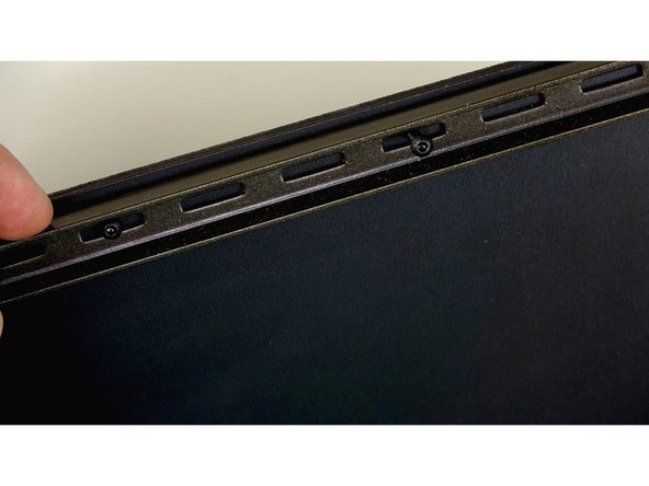
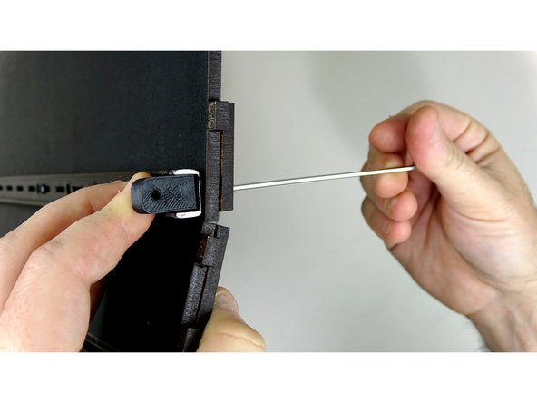
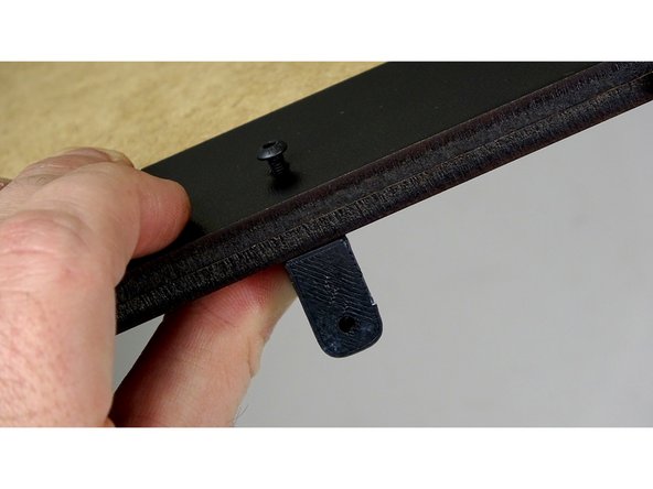
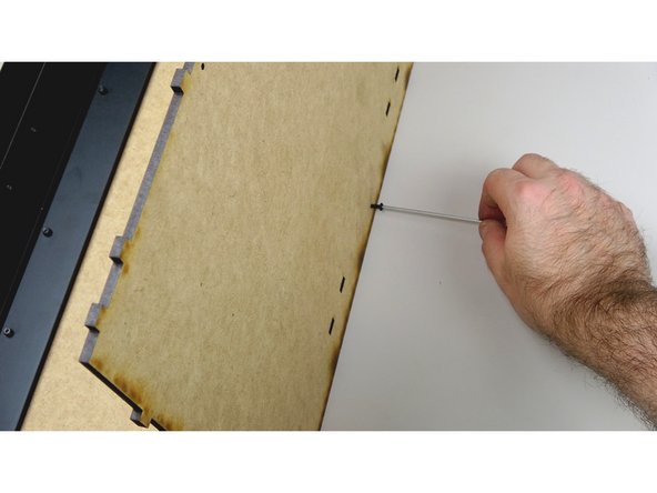
Insert a square nut into the top of two of the 3D Printed L brackets. Set these aside for now.
-
Use the allen wrench to push the square nut all the way down until the hole of the nut aligns with the holes on the bracket.
-
-
-
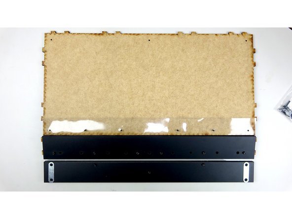
Take the Base Panel and lay it flat on the table with the finished side UP. Place the Steel support beam along the edge of the Base panel that does NOT have any tabs.
-
The Steel Support Beam may have sharp burs or edges on the ends from the manufacturing process. These are covered up during assembly, but use caution while they are exposed.
-
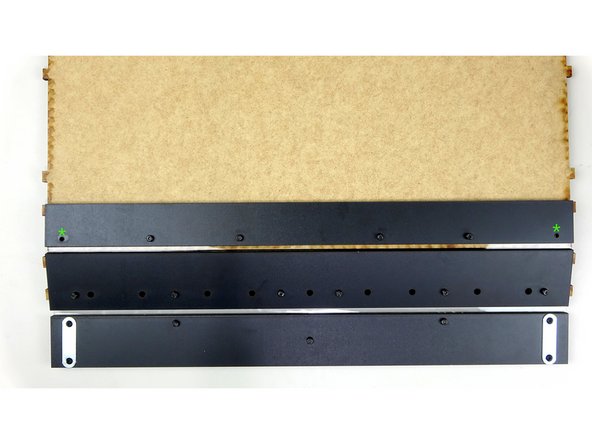
Insert four, 16mm bolts through the Steel support beam and Base panel. There are six holes total, so leave the holes on the very ends empty and insert the bolts into the other 4 remaining holes (as shown in 2rd picture)
-
-
-
Flip the Base panel over to where the unfinished side is facing up, being careful to keep the 4 inserted bolts and Steel support beam in place underneath. There should be enough bolt sticking up through the top of the Base panel to complete this step.
-
Take the Face assembly, constructed in STAGE 1, and with it FACE DOWN (logo facing down) start pushing the bolts through the vinyl hinge. The vinyl should help keep the bolts in place for the next step as you push them through.
-
Take the Front Tack Guide panel and line it up with the base panel and bolts. Lay it on top of the Base panel, sandwiching the vinyl in between. Secure the four bolts in place with four nylock nuts (as pictured).
-
The bolt holes on the ends should still be empty. We will be using these in the next step.
-
Check your work: Make sure the orientation of all the panels match up like the last picture. You want the unfinished part side of the Base panel to be on the same side as the Maglock plates on the Face assembly.
-
-
-
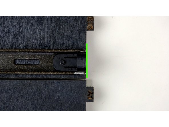
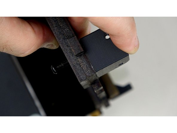
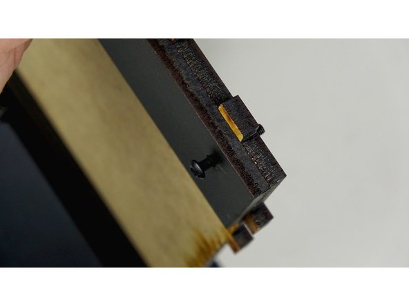
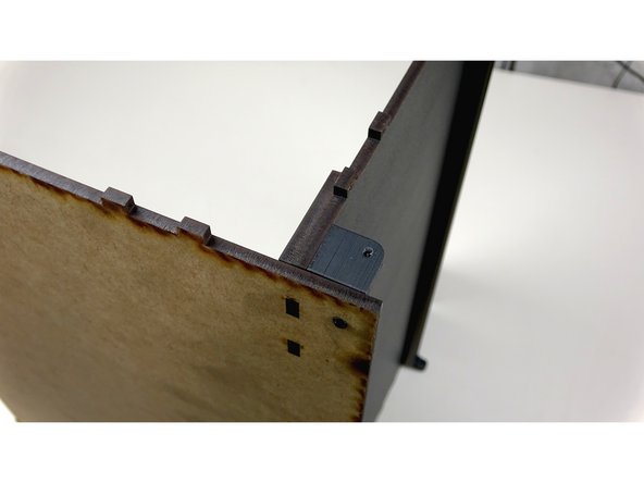
Place one of the prepared L brackets inside of the steel support beam facing outward. Secure it in place using one of the 20mm bolts. Insert the bolt from the opposite end so it catches the square nut in the bracket.
-
Repeat this step for the other end of the support beam.
-
Make sure the L brackets and steel support beam are flush with the sides of the Base panel as pictured.
-
Tighten down the bolts and nuts connecting the vinyl to the Base panel.
-
The Bolts and Nuts on the Face Assembly should still be a little loose. This will aid in assembly later.
-
-
-
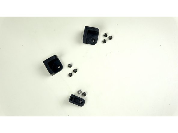
For this step you'll need the two 3D printed corner brackets and the last L bracket. You'll need 3 nylock nuts for each corner bracket, and a nylock nut for the L bracket. You will also need one square nut for the L bracket.
-
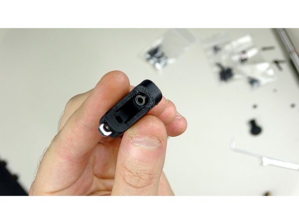
Insert the nylock nuts into the Corner brackets and L bracket. Insert the Square nut into the L bracket.
-
If you have difficulty getting the nylocks into the cutouts, you can use a 10mm bolt inserted from the opposite end to tighten down the nylock into the cutout. Just be careful not to strip the cutout.
-
The brackets may have some excess filament where it sat on the bed of the 3D printer. Cut away this 'Elephants foot' with the craft knife to ensure the brackets are flush on all sides.
-
-
-
The Brackets are going to mount to the BOTTOM of the Base panel (finished side)
-
Line up the Rear Track Guide panel with the bolt holes on the back of the base panel. It will be mounted on the UNFINISHED side of the base panel.
-
After lining up the Rear Track Guide on the unfinished side of base panel, insert 16mm bolts through the rear track guide and base panel.
-
Screw on the Corner Brackets. One on each end, and the L bracket in the center. You should be screwing into the side of the L Bracket that contains the square nut, leaving the nylock nut side for use later.
-
-
-
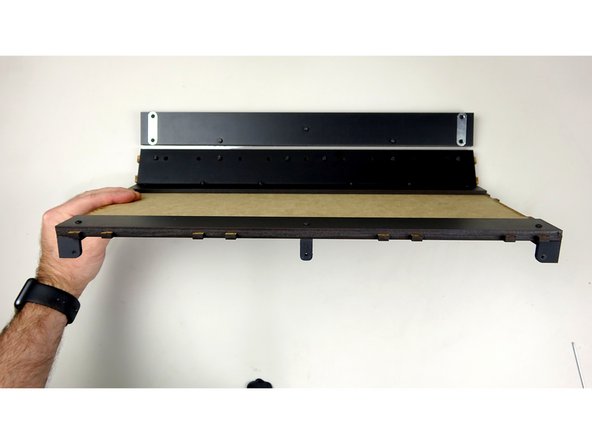
Check to make sure you have the Rear Track Guide on correctly. It should be on the unfinished side of the base panel, with its own finished side facing up. So they should be unfinished side against unfinished side.
-
Take a look at the last image. Your assembly should look like this at this stage. Take note of panel orientations and positions of brackets.
-
-
-
You will need the Rear Track Guide panel, Back Panel, and 12mm bolts for this step.
-
Lay the Back panel down, finished side up, and then insert the finished Base assembly into the tab holes as pictured.
-
Carefully stand the whole assembly upright, with the base panel on the table.
-
Use three, 12mm bolts to affix the Back panel to the Base panel. They should go from the back, through the Back panel, and catch the nylocks in the corner brackets and the l bracket.
-
-
-
Done! Set this assembly aside for now. We'll grab it again later in the build.
-
-


Cancel: I did not complete this guide.
3 other people completed this guide.

2 Comments
In step 1, you have the yellow square showing the Front Track Guide Panel but have it labeled on the side as the Rear Track Guide Panel. Rear Track Guide Panel is missing from the picture.
In Step 1 it doesn’t list the 3 12mm bolts needed in Step 9.
Step 7 its not clear which nut (square or nylock) to screw into on the L-bracket, if its not important might be worth noting that it doesn’t matter.
Sean Deuell - Resolved on Release Reply