
-
-
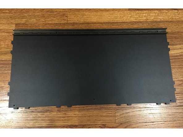
Finished STAGE 1 Face Assembly
-
Fasteners: 16mm bolts, Nylock Nuts, Square Nuts
-
3D Printed Universal Brackets
-
Steel Base Support Beam
-
Front Track Guide
-
Base Panel
-
Rear Track Guide
-
-
-
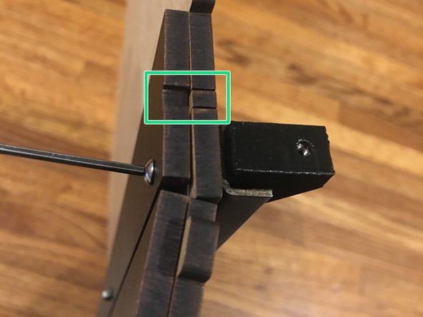
At the heart of the RepBox fastening system is what we call the "Universal Bracket." It may be configured to hold 2-3 panels together depending on the location. 2 corner junctions require a square nut to be pressed into both ends of the bracket. 3 corner junctions at the bottom rear of the box require a square nut pressed into the center as well.
-
Use the allen wrench to push the square nut all the way down until the hole of the nut aligns with the holes on the bracket.
-
Press 2 square nuts in either end of a bracket for the front corners and rear center support. 3 Universal brackets total.
-
Press 3 square nuts into both ends AND the center of two brackets for the tri-corner junction at the bottom rear of the box. 2 Universal brackets total.
-
-
-
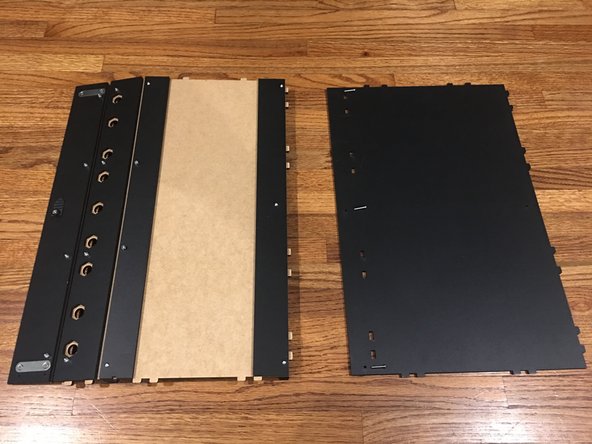
Take the Base Panel and lay it flat on the table with the finished side UP. Place the Steel support beam along the edge of the Base panel that does NOT have any tabs.
-
The Steel Support Beam may have sharp burs or edges on the ends from the manufacturing process. These are covered up during assembly, but use caution while they are exposed.
-
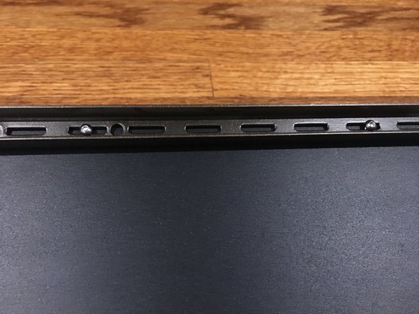
Insert two, 16mm bolts through the Steel support beam and Base panel. There are four holes total, so leave the holes on the very ends empty and insert the bolts into the 2 center holes (as shown in 2nd picture)
-
-
-
Flip the Base panel over to where the unfinished side is facing up, being careful to keep the 2 inserted bolts and Steel support beam in place underneath. There should be enough bolt sticking up through the top of the Base panel to complete this step.
-
Take the Face assembly, constructed in STAGE 1, and with it FACE DOWN (logo facing down) start pushing the bolts through the vinyl hinge. The vinyl should help keep the bolts in place for the next step as you push them through.
-
Take the Front Tack Guide panel and line it up with the base panel and bolts. Lay it on top of the Base panel, sandwiching the vinyl in between. Secure the bolts in place with nylock nuts (as pictured).
-
The bolt holes on the ends should still be empty. We will be using these in the next step.
-
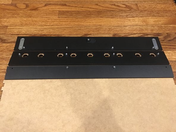
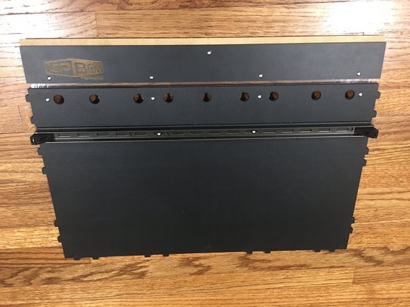
Check your work: Make sure the orientation of all the panels match up like the last picture. You want the unfinished part side of the Base panel to be on the same side as the Maglock plates on the Face assembly.
-
-
-
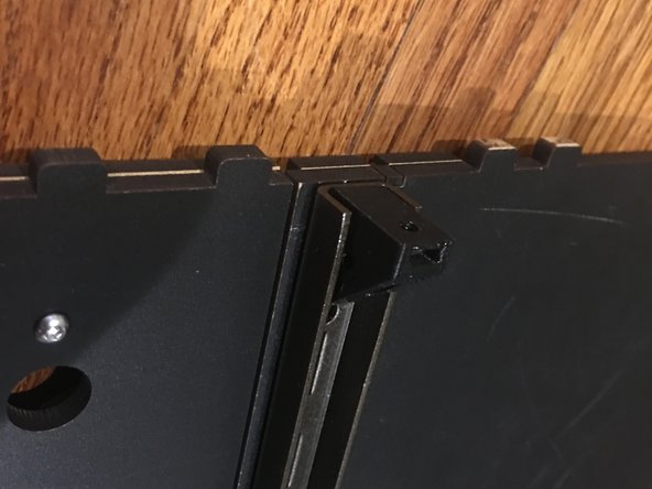
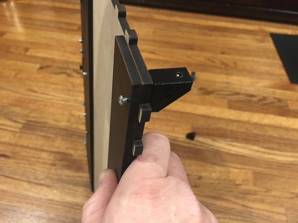
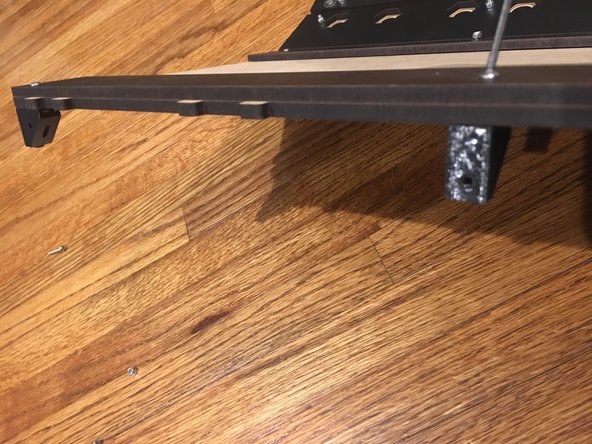
Place one of the prepared L brackets inside of the steel support beam facing outward. Secure it in place using one of the 16mm bolts. Insert the bolt from the opposite end so it catches the square nut in the bracket.
-
Repeat this step for the other end of the support beam.
-
Make sure the L brackets and steel support beam are flush with the sides of the Base panel as pictured.
-
Tighten down the bolts and nuts connecting the vinyl to the Base panel.
-
You'll notice there's a knockout in both the front track guide and the base panel now. This is designed for use as a wiring channel for the optional lighting kit that's coming soon and should be left in place for now. If you're really concerned about air incursion consider using silicone caulk to seal all the joints once your RepBox is assembled.
-
-
-
This step uses the Universal Brackets that were pressed with three square nuts in the earlier preparation step.
-
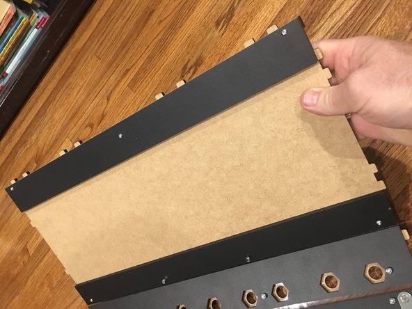
Line up the Rear Track Guide panel with the bolt holes on the back of the base panel. It will be mounted on the UNFINISHED side of the base panel.
-
After lining up the Rear Track Guide on the unfinished side of base panel, insert 16mm bolts through the rear track guide and base panel.
-
Screw on the brackets with 3 square nuts pressed in. One on each end, and the remaining bracket with only two squared nuts pressed in each end in the center.
-
-
-
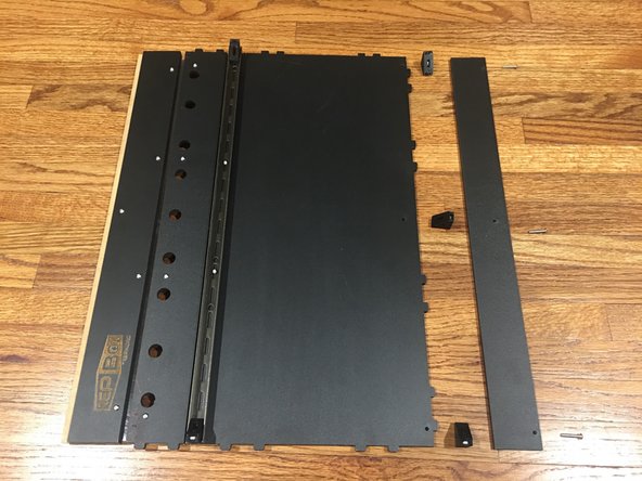
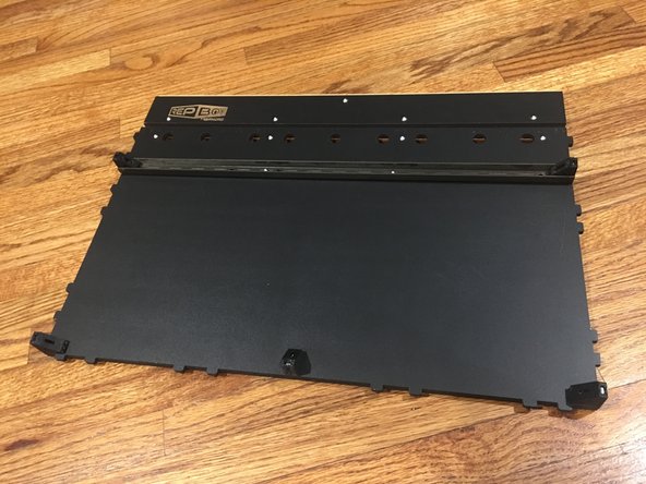
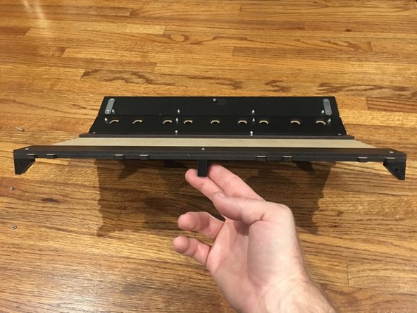
Check to make sure you have the Rear Track Guide on correctly. It should be on the unfinished side of the base panel, with its own finished side facing up. So they should be unfinished side against unfinished side.
-
Take a look at the last two images. Your assembly should look like this at this stage. Take note of panel orientations and positions of brackets.
-
-
-
You will need the Rear Track Guide panel, Back Panel, and 16mm bolts for this step.
-
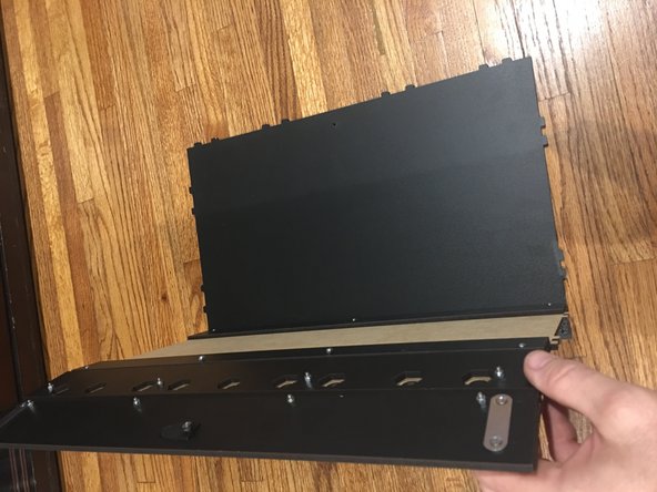
Lay the Back panel down, finished side up, and then insert the finished Base assembly into the tab holes as pictured.
-
Carefully stand the whole assembly upright, with the base panel on the table.
-
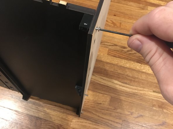
Use three, 16mm bolts to affix the Back panel to the Base panel. They should go from the back, through the Back panel, and catch the square nuts pressed into the brackets attached to the base panel in the previous step.
-
-
-
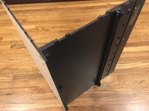
Done! Set this assembly aside for now. We'll grab it again later in the build.
-
Go on to stage 3!
-


Cancel: I did not complete this guide.
2 other people completed this guide.
