
-
-
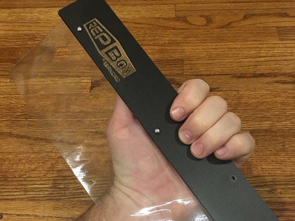
Inner and Outer Face Plates
-
Inner and Outer Exit Plates
-
Large Vinyl Hinge
-
Fastener Bag Containing: 16mm Bolts (The longer of the two button head screws in the fastener bag), M3 Nylock Nuts, 1/4" phillips head screws
-
Metal Maglatch Plates
-
Allen Wrench and 3D Printed Nut driver
-
Seal Kit Parts: 3D Printed Strike Plate, 16mm bolt
-
-
-
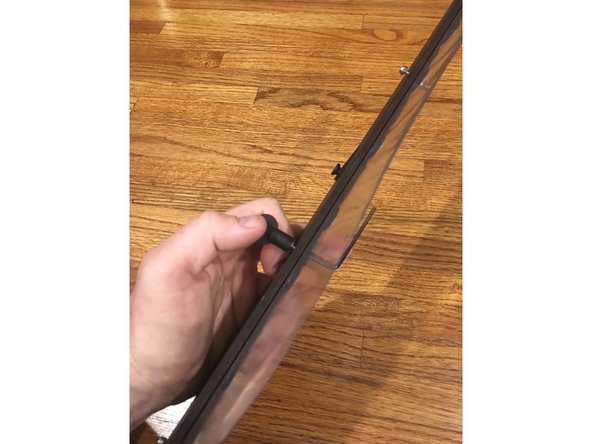
Make sure you've removed all of the nylon punch-outs from the hinge as noted in STAGE 0 preparation.
-
The vinyl hinges may slightly expand/contract with temperature. This is normal. When you line up the holes you may need to stretch it slightly to reach the holes. The easiest way to do this is to place over one end bolt first and then stretch to the opposite end and place that bolt. Middle holes should line up correctly afterwards.
-
FOR SEAL KIT VERSION SKIP TO STEP 3
-
Place the Outer Face plate (with Repkord logo) on TOP of the Large Vinyl Hinge as pictured. Check for proper hole alignment. The vinyl sheet is cut so that its reversible so you can't install it upside down, however only one set of 3mm holes will line up properly with the faceplates. Verify that all your holes line up before bolting.
-
Flip the whole thing over, so that now the logo is facing the table and the vinyl is between you and the plate as pictured.
-
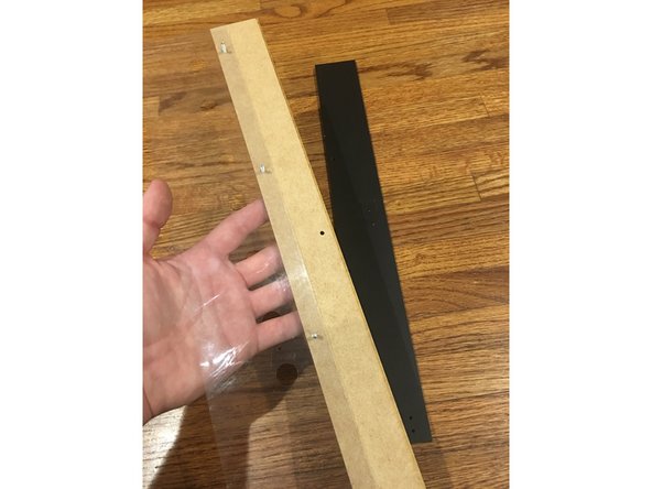
Place the Inner Face Plate on TOP of the vinyl sheet, above the Outer Face Plate as pictured with the finished side facing DOWNWARD so that when its flipped over only black is visible. There WILL BE extra height to the back panel. This is normal for the standard kit.
-
If the strike plate punch-out has come loose locate it in the box and bolt it on as pictured with a 16mm bolt and nylock.
-
-
-
Standard kit owners skip to step 4
-
Place the Outer Face plate (with Repkord logo) on TOP of the Large Vinyl Hinge as pictured. Make sure to note proper hole alignment. The vinyl sheet is cut so that only one side lines up correctly with the holes in the panel.
-
Flip the whole thing over, so that now the logo is facing the table and the vinyl is between you and the plate as pictured.
-
PUNCH OUT THE STRIKE PLATE KNOCKOUT FIRST and then place the Inner Face Plate on TOP of the vinyl sheet, above the Outer Face Plate as pictured with the finished side facing DOWNWARD so that when its flipped over only black is visible. There WILL BE extra height to the back panel. This is normal.
-
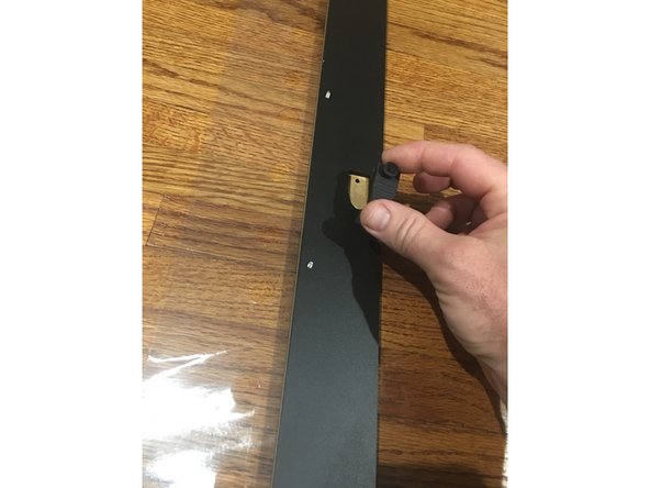
Insert a square nut into the top of the 3D printed strike plate included in the Misc Parts bag and bolt it through the hole on the inner faceplate to the outer using a 16mm bolt and nylock.
-
-
-
This process is the same for both the standard and seal kit versions. The only difference is the orientation of the rear faceplate and the installation of the strike plate on the seal kit. Note that the finished side may look different from what's pictured depending on what version you have.
-
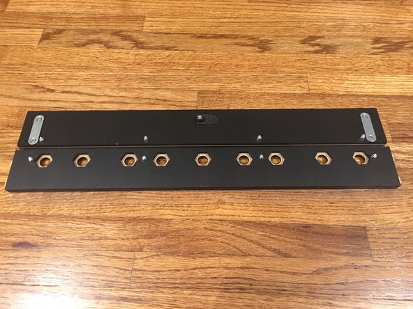
Place five 16mm bolts in each of the available holes and cap them on the inner faceplate side with nylocks.
-
Be sure the left and right edges of the faceplates line up flush. Using the included Allen wrench (hex key) and 3D Printed nut driver, tighten down the bolts and nuts.
-
The top of the rear faceplate will overhang the front faceplate. This is normal.
-
-
-
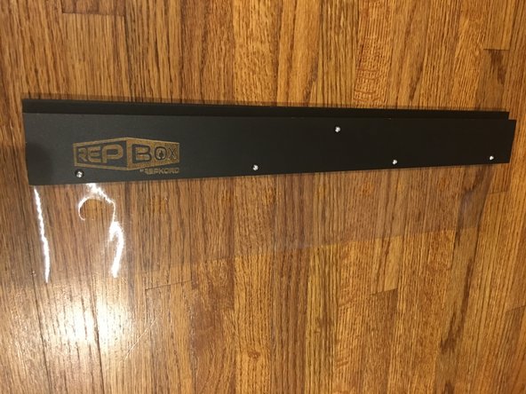
The position of the maglatch plates will vary depending on whether or not you have the standard or seal kit version. Please be sure to follow the instructions for the kit you have below.
-
STANDARD KIT
-
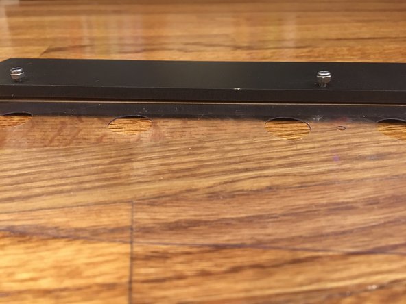
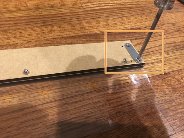
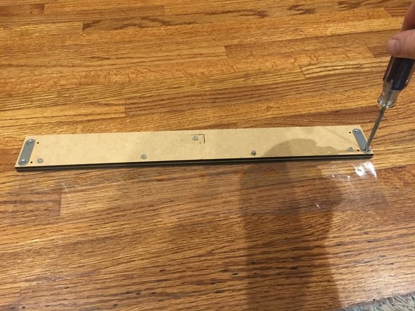
Note that there are four holes on the outer edges of the rear faceplate. Using the 1/4" phillips head screws from the fastener bag and a screwdriver, fasten the maglatch plates to the ends of the rear faceplate CLOSEST TO THE EDGE. Repeat this process for both sides.
-
SEAL KIT
-
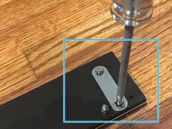
Note that there are four holes on the outer edges of the rear faceplate. Using the 1/4" phillips head screws from the fastener bag and a screwdriver, fasten the maglatch plates to the ends of the rear faceplate using the set of holes that are FURTHEST FROM THE EDGE (CLOSER TO THE CENTER). Refer to Pic 2. Repeat this process for both sides.
-
-
-
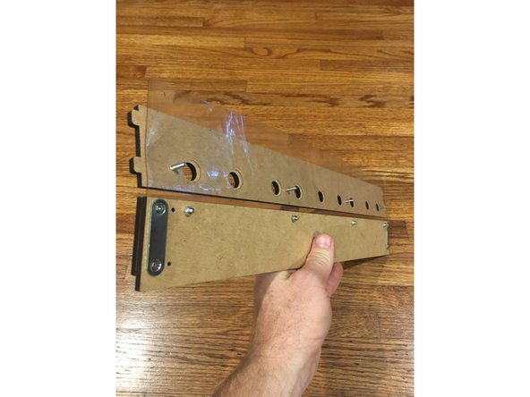
With everything face down (logo down), place the Outer Exit Plate (the one WITH tabs) under the vinyl sheet as pictured.
-
Insert four, 16mm bolts through the plate and through the vinyl sheet.
-
Place the Inner Exit Plate on top of the vinyl, being careful to line up the bolts with the holes as pictured.
-
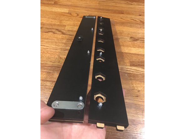
Secure the plates using 6 nylock nuts. Verify that the ends of the exit plates line up and tighten the bolts.
-
The edge of the faceplate and the edge of the exit plates SHOULD NOT line up. The faceplate should be about 2mm shorter on either end. This is normal.
-
Check you work: The Maglock plates should be on the opposite side of the Repkord logo. The Exit plate with the tabs should be on the SAME side as the logo. The Exit plate without the tabs should be on the same side as the Maglock plates. If everything looks good its time to move on to the next Stage!
-


Cancel: I did not complete this guide.
4 other people completed this guide.
