
Introduction
PLEASE NOTE: THIS GUIDE IS IN PROGRESS. Please check back often for updates.
Tools
Parts
No parts specified.
-
-
Please watch the build video for in depth instructions - https://youtu.be/BDDXVMv4M0A .
-
An interactive CAD model is available and is also very helpful - https://repkord.com/RBTTv2-3D .
-
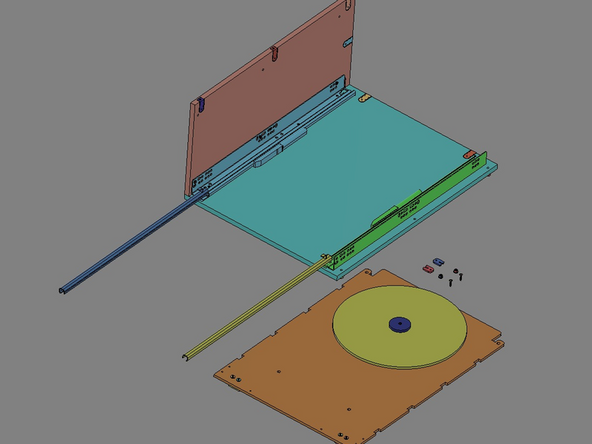
IMG 1 - Unpack all the parts and confirm all parts are available.
-
Locate the Printed Bill of Material and refer to it for part/location information.
-
Locate a clean/flat surface with plenty of room to work.
-
-
-
IMG 1 - Locate Panel 8.
-
IMG 2 - Pop-out the internal pieces from the center of Panel 8. For v2.0, there are six pieces (highlighted in Green) that should be saved. The scrap material should also be saved for a later Step.
-
IMG 3 - Pop-out the internal pieces from the center of Panel 8. For v2.1, there are eight pieces (highlighted in Orange) that should be saved. The scrap material should also be saved for a later Step.
-
-
-
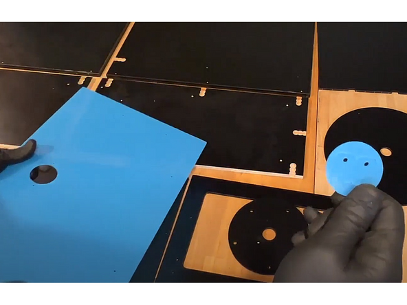
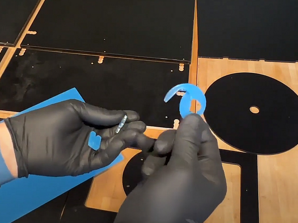
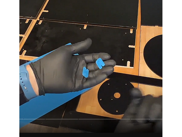
IMG 1 - Locate the Acrylic Lid and remove the circle knock-out.
-
IMG 2 - Remove the two Tray Clips from within that circle.
-
IMG 3 - These are the Tray Clips.
-
Carefully remove the protective film from all of the acrylic parts.
-
-
-
Remove the protective film from both sides of the Acrylic lid.
-
-
-
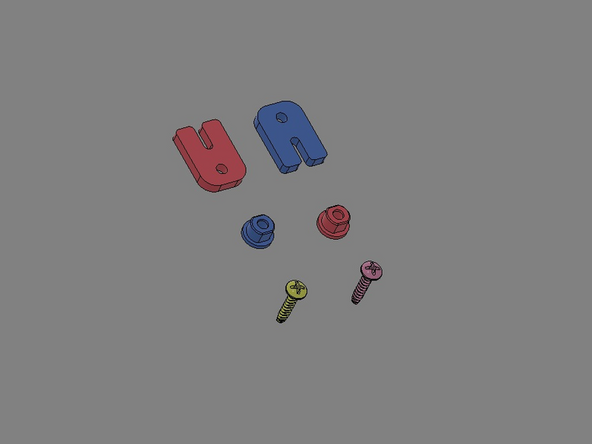
IMG 1 - Locate the Butt Anchors from within the Plastic Parts Pack.
-
IMG 2 - Align the Butt Anchors with the notches in a body panel. There are four panels total; Top, Bottom and two Side Panels.
-
IMG 3 - Initially, install the anchors by hand. These Butt Anchors must sit flush with the surface of the panels; If needed, use the scrap piece from Step 1 to cover the anchor and gently tap them in place with a hammer/mallet.
-
Repeat this process for the remaining panels.
-
-
-
Do Not Use Power Tools for assembly.
-
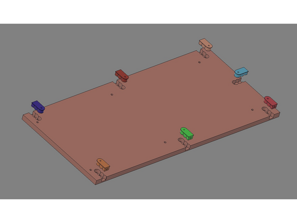
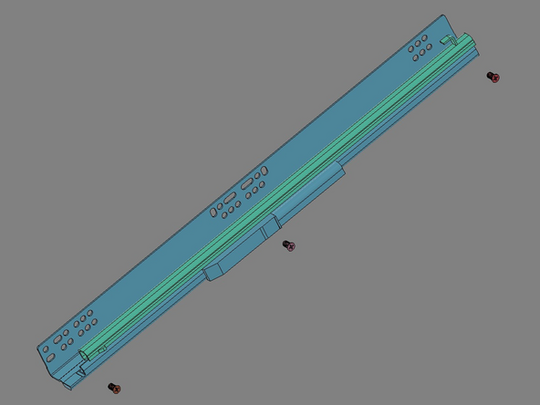
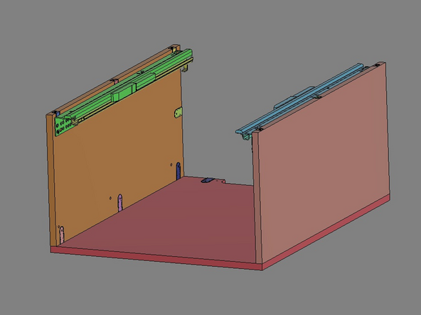
IMG 1 - Locate the Glide Pack and take one of the two (Left Side shown). Locate x3 of the Glide Screws.
-
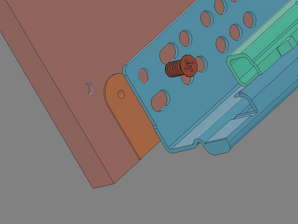
IMG 2 - Align the Left Glide with a Side Panel with the finished face forward. The first hole in the Left Glide will align with the first hole in the Side Panel.
-
Do not over tighten any of the Glide Screws. Bring them down slowly and seat them against the glide.
-
IMG 3 - Install x2 Glide Screws into the two remaining holes in the Side Panel; one in the middle and one at the rear.
-
Confirm the orientation of the Glide. There is a small hook-feature that should be at the back (unfinished edge) of the Side Panel (highlighted in Green).
-
Mirror the process with the Right Glide into the other Side Panel.
-
-
-
Do Not Use Power Tools for assembly.
-
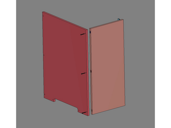
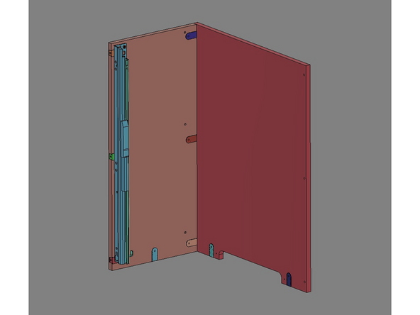
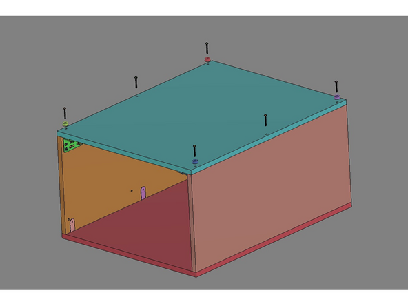
IMG 1 - Locate the 25mm TF Screws. Align the Left Side Assembly with the Top Panel and secure them together with x3 25mm TF Screws. The screws should pass through the Top Panel an into the Butt Anchors.
-
Top simplify this process stand the parts up. The rear edges (unfinished) of these panels should be facing down towards the work surface.
-
IMG 2 - Confirm the correct orientations.
-
IMG 3 - Mirror these steps for the Right Side Assembly.
-
-
-
Do Not Use Power Tools for assembly.
-
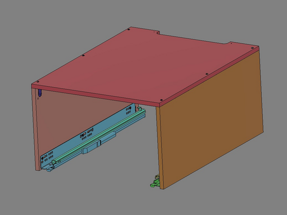
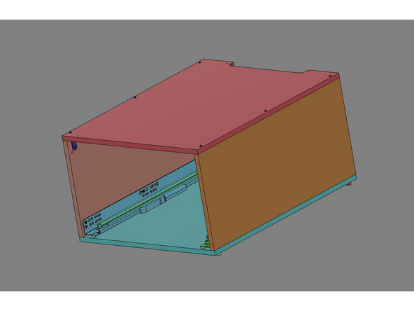
IMG 1 - Flip the Main Assembly up-side-down.
-
IMG 2 - Locale the x4 Rubber Feet and x6 25mm TF Screws. Align the Bottom Panel with the Main Assembly and secure it with x2 25mm TF Screws in the middle holes, but do not tighten.
-
Place a Rubber Foot at each corner hole and secure them to the Main Assembly using the remaining screws. Now, tighten the two middle 25mm TF Screws.
-
IMG 3 - Flip the Main Assembly over to be top-side-up and confirm the orientations.
-
-
-
Do Not Use Power Tools for assembly.
-
IMG 1 - Locate the Exit Panel, x2 25mm TF Screws, x2 Flange Nuts and the Exit Pack which contains the Exit Fittings and Exit Plugs.
-
It is suggested that any Exit Plugs needed should be installed prior to the next step. Alternatively, they can all be installed now then removed later as needed.
-
IMG 2 - Align the Exit Panel with the flat side facing the rear of the Main Assembly. The x2 Flange Nuts will fit up into the Exit Panel from the bottom.
-
IMG 3 - Secure the Exit Panel using x2 25mm TF Screws though the Top Panel into the Flange Nuts.
-
-
-
Do Not Use Power Tools for assembly.
-
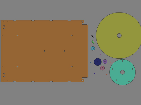
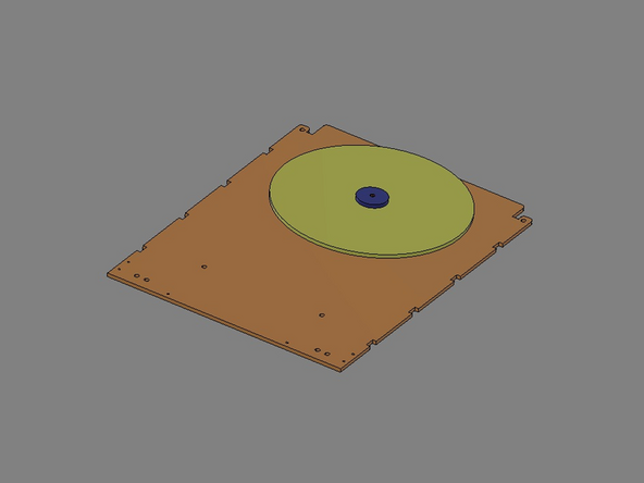
IMG 1 - Locate the following: Tray, x1 16mm TF Screw, Hub Flange Nut, Turntable Hub Spacer, x5 Ball Bearings, Hub Topper (either the 32mm or 50mm), x2 6mm Turntable Hub Spacers, Turntable and Bearing Race.
-
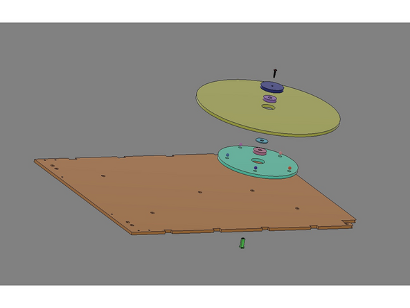
IMG 2 - The parts will stack/align as shown. Note that the Hub Flange Nut will come up through the bottom of the Tray utilizing the rear most hole.
-
Insert the Hub Flange Nut into the tray and set the tray down on a flat surface with the protruding Hub Flange Nut facing UP.
-
Stack x1 6mm Turntable Hub Spacer onto the protruding Hub Flange Nut, followed by the Turntable Hub Spacer and then the remaining 6mm Turntable Hub Spacer.
-
Place the Bearing Race onto the Stack. Insert the x5 Ball Bearings into the five holes of the Bearing Race. Place the Turntable onto the Stack.
-
Place the Hub Topper (either the 32mm or 50mm) on top of the Stack and fasten it using the 16mm TF Screw.
-
The Turntable should now rotate freely, but be captured by the Hub Topper.
-
-
-
Do Not Use Power Tools for assembly.
-
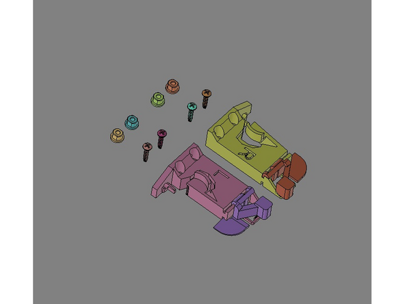
IMG 1 - Locate the Right and Left Glide Latchs, x4 Flange Nuts and x4 16mm TF Screws.
-
Flip the Tray Assembly over with the Turntable facing DOWN.
-
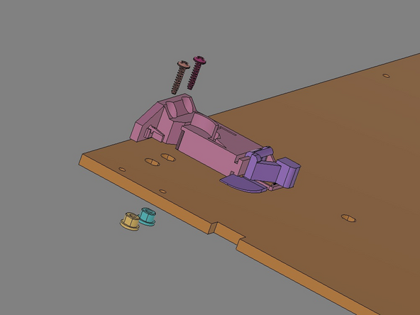
IMG 2 - Align a Glide Latch as shown. The x2 Flange Nuts will be inserted into the Tray from the bottom. The x2 16mm TF Screws will insert through the two hole in the Glide Latch, though the Tray and into the Flange Nuts.
-
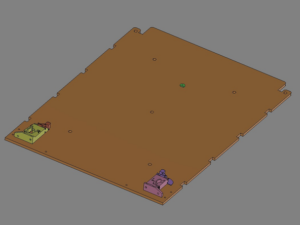
IMG 3 - Repeat the process for the other Glide Latch.
-
Verify the Glide Latches are oriented correctly.
-
-
-
Do Not Use Power Tools for assembly.
-
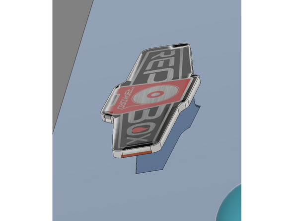
IMG 1 - Locate the Drawer Front Trim, Clear Drawer Front, x2 Handles (with their included screws) and the Dome Label.
-
IMG 2 - Lay the Drawer Front Trim on a flat surface (with the engraved lines facing upward). Peel the protective backing from the Dome Label. Align the label with the engraved marks on the Drawer Front Trim (the label will cover all of these lines). Press the label firmly onto the surface.
-
The Handel Screws are specific to the Handles. Only use their provided screws for the Handles.
-
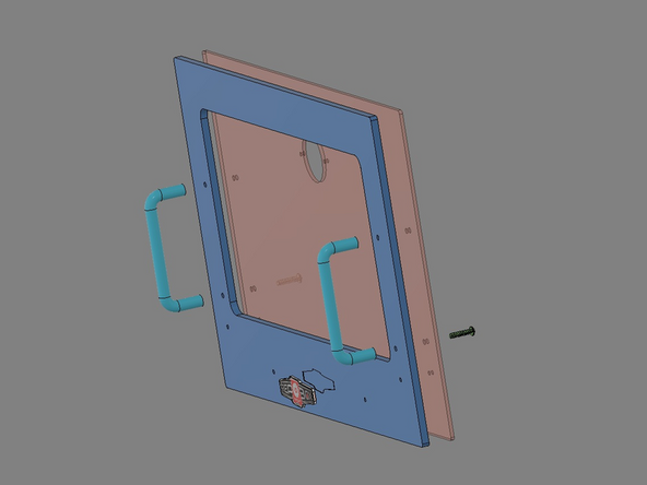
IMG 3 - Align the Clear Drawer Front with the BACK of the Drawer Front Trim. Align one of the Handles (as shown) and install ONE of the Handle Screws in the LOWER hole.
-
Repeat the process for the other Handle.
-
Do NOT install the remaining two Handle Screws in the upper holes yet.
-
-
-
Do Not Use Power Tools for assembly.
-
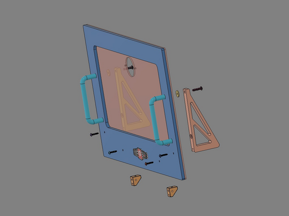
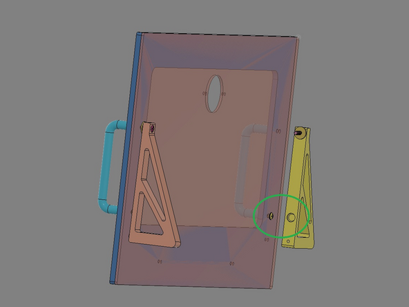
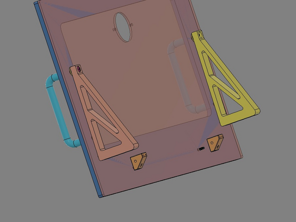
IMG 1 - Locate x2 Alignment Brackets, x2 Brackets, x2 Bracket Spacer, x4 16mm TF Screws and the two remaining Handle Screws.
-
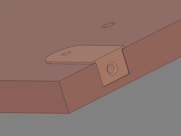
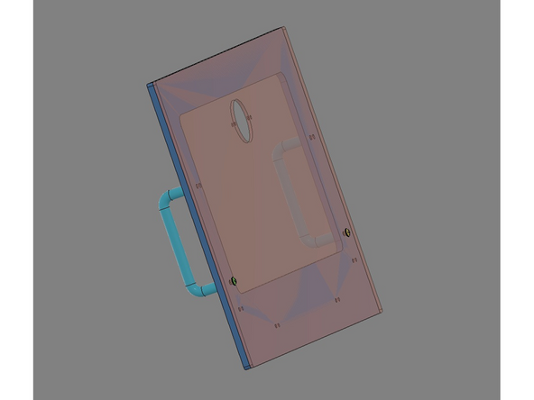
IMG 2 - Align the recess in the Alignment Bracket with the Handle Screw installed in the previous Step (highlighted in Green).
-
Insert a remaining Handle Screw into the top hole of the Alignment Bracket and through a Bracket Spacer. This screw will continue through the Drawer Front Assembly and into the Handle.
-
Do not fully tighten the top Handle Screws at this time. they will be used to adjust the Draw Front Assembly in a later Step.
-
Repeat the process for the other Handle.
-
IMG 3 - Insert x2 16mm TF Screws into the Drawer Front Assembly and into the Alignment Bracket (highlighted in Orange).
-
-
-
Do Not Use Power Tools for assembly.
-
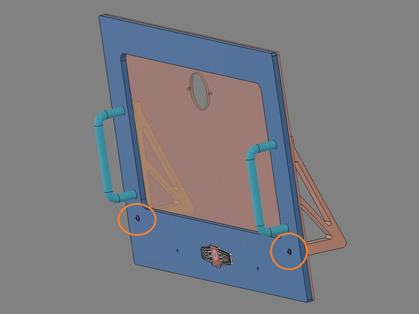
IMG 1 - Locate x2 16mm TF Screws and x2 Brackets.
-
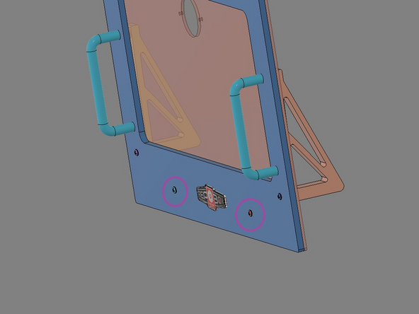
IMG 2 - Insert these screws though the remaining holes in the Lid Assembly (highlighted in Purple).
-
IMG 3 - The x2 16mm TF Screws should be tightened into the LOWER hole of the brackets x2.
-
Do not fully tighten these two screws.
-
-
-
Do Not Use Power Tools for assembly.
-
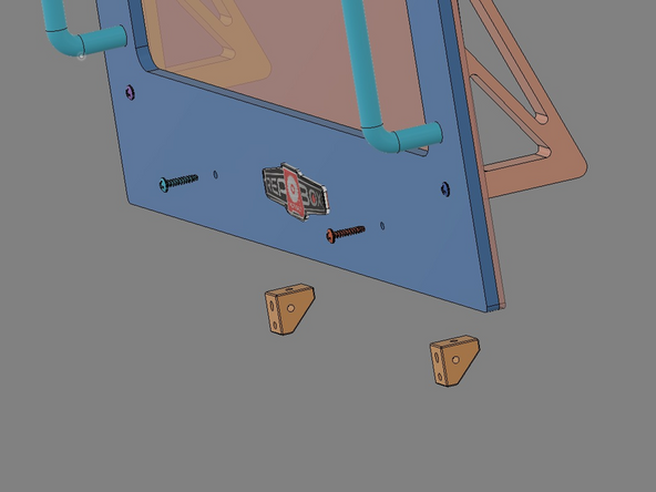
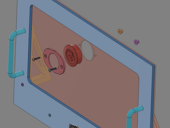
IMG 1 - Locate x2 16mm TF Screws, the Lid Trim Clamp, Hygrometer and x2 Flange Nuts.
-
For v2.0, install the Hygrometer into the Drawer Front Assembly from the front. v2.1 does not come with a Hygrometer, but install the Lid Trim Clamp in the same way over top of the engraved Repkord Logo.
-
Note that the Lid Trim Clamp has a recess on one side. This recess will fit around the Hygrometer once installed.
-
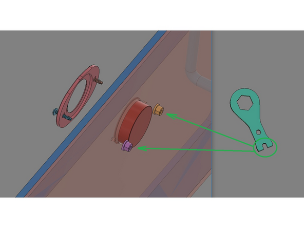
IMG 2 - Align the x2 16mm TF Screws with the Lid Trim Clamp. Place the Lid Trim Clamp over the Hygrometer. The x2 16mm TF Screws will pass through the Lid Trim Clamp through the holes in the Acrylic Lid and into the x2 Flange Nuts. Hold the flange nuts in place with PART 14 Drumstick Tool.
-
Be sure to rotate the Hygrometer for best view as the x2 ''16mm TF Screws" are slowly tightened.
-
Be sure not to over tighten these screws. They should be just tight enough to secure the Hygrometer and prevent it from rotating out of view.
-
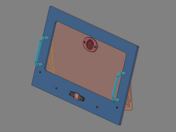
IMG 3 - The Drawer Front Assembly is now complete.
-
-
-
The Top and Right Side have been removed from view to provide better visibility. They DO NOT need to be remove to complete the assembly.
-
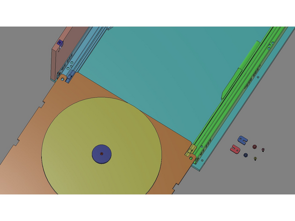
IMG 1 - Extend the Glide top rails to their full extension. Have the Tray Assembly ready (Turntable side up).
-
IMG 2 - Set the Tray Assembly onto the Glide top rails and align the Tray Assembly with the Glide top rail hooks.
-
IMG 3 - Reach under the Tray Assembly and pull the Glide top rail forward and insert it into the Glide Latch. There should be an audible clinking-in once the Glide top rail is fully inserted.
-
The plastic tip (shown in Green) is pre-installed into the Glide top rail.
-
Repeat the process for the other Glide top rail.
-
The Tray Assembly is NOT fully secure at this point.
-
-
-
Do Not Use Power Tools for assembly.
-
Slowly push the Tray Assembly & Glide top rails back into the box.
-
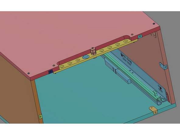
IMG 1 - Locate x2 Tray Clips, x2 Flange Nuts and x2 16mm TF Screws.
-
IMG 2 - Align one Flange Nut with the hole in the back corner of the Tray Assembly.
-
IMG 3 - Fit the Tray Clip around the Glide top rail hook. Insert the 16mm TF Screw into the Tray Clip, through the Tray and into the Flange Nut.
-
Do Not over tighten this screw. It should be just tight enough to keep the Tray Clip secure.
-
Repeat the process for the other side of the Tray Assembly.
-
The Tray Assembly should now be secure to the Main Assembly.
-
-
-
Do Not Use Power Tools for assembly.
-
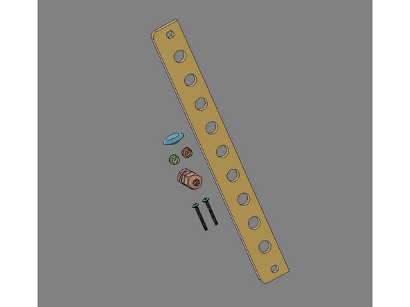
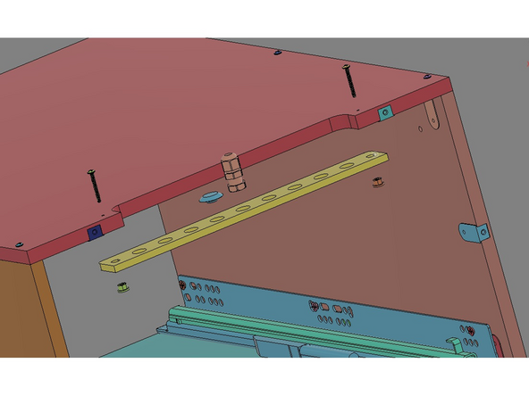
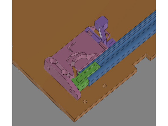
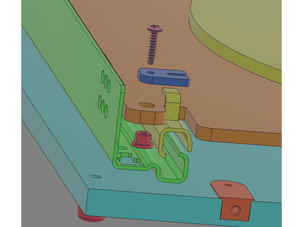
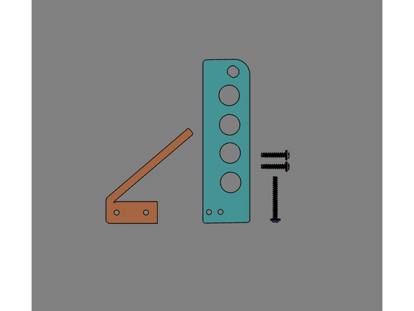
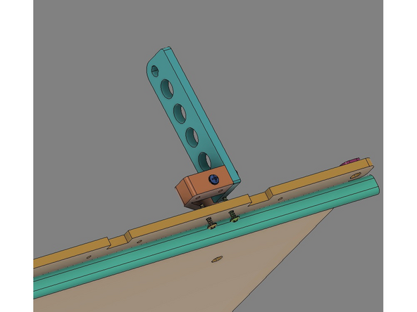
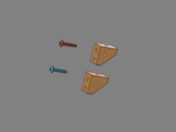
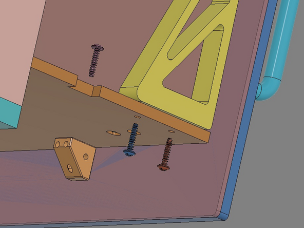
IMG 1 - Locate the Brake, Tower, x1 25mm TF Screw and x4 16mm TF Screws.
-
These images are for installing the finished Brake/Tower assembly on the Right side of the TT. These parts can be reversed if the Brake/Tower is to be installed on the Left side of the TT.
-
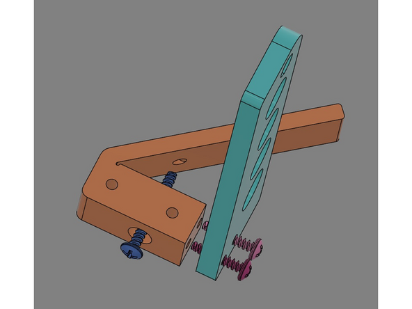
IMG 2 - Insert the x1 25mm TF Screw into the single side-hole as shown. When tightening, leave a small gap between the screw tip and brake arm (as shown).
-
IMG 2 cont. - Insert the x2 16mm TF Screw through holes in the Tower and secure the Tower to the Brake.
-
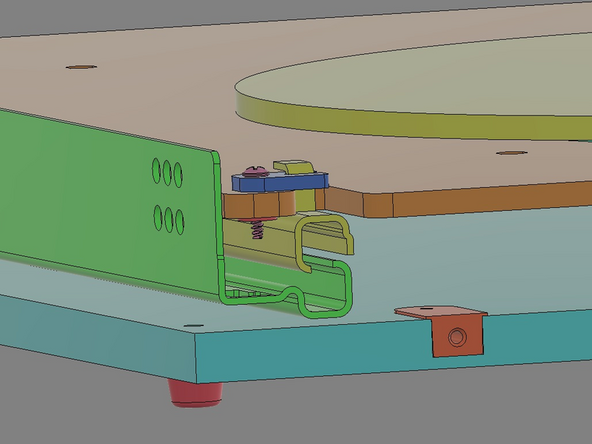
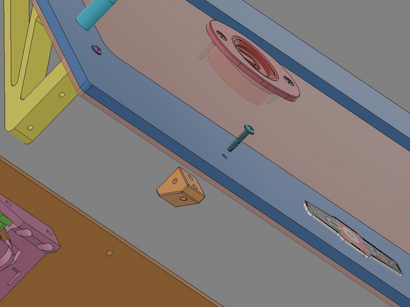
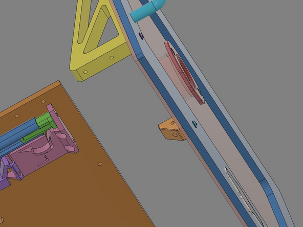
IMG 3 - To attach the Brake/Tower Assembly to the Tray Assembly, insert the x2 16mm TF Screws up through the Tray Assembly (using the rear-most pair of holes) then up into the Brake/Tower Assembly.
-
The x1 25mm TF Screw can be slowly tightened so the brake arm gently drags against the side of the Turn Table. This drag should be adjust just enough to keep a spool of filament from "free wheeling" as the filament is pulled through and up to the printer.
-
-
-
Do Not Use Power Tools for assembly.
-
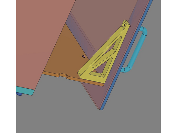
IMG 1 - Locate the x2 Brackets and x2 '16mm TF Screws''.
-
IMG 2 - Align one 16mm TF Screw with the Drawer Front Assembly. Orient one Bracket as shown.
-
IMG 3 - Insert the 16mm TF Screw through the Drawer Front Assembly and into the LOWER hole in the Bracket to secure it.
-
Repeat this process for the other side of the Drawer Front Assembly.
-
Confirm the Bracket orientations before moving to the next step.
-
-
-
Do Not Use Power Tools for assembly.
-
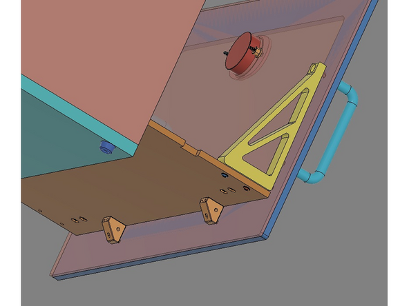
IMG 1 - Locate x6 16mm TF Screws. They will be aligned as shown on both sides of the Drawer Front Assembly.
-
Some parts have been removed from these images to provide better visibility for the next instructions. They DO NOT need to be remove to complete the assembly.
-
IMG 2 - Slide the Drawer Front Assembly onto the Tray Assembly and align the Alignment Brackets with the holes in the Tray (as shown). This will also align the lower Brackets with the two holes at the front of the Tray.
-
IMG 2 - Insert two of the 16mm TF screws into the two front holes of the Tray and into the Brackets. Tighten these screws slowly making any adjustment necessary for alignment. DO NOT fully tighten these screws yet.
-
IMG 2 - Insert two of the 16mm TF screws into the two side holes of the Tray and one of the Alignment Brackets. Tighten these screws slowly making any adjustment necessary for alignment. DO NOT fully tighten these screws yet.
-
Repeat this for the other Alignment Bracket.
-
Once all six screws have been installed, slowly tighten them all to fully secure the Drawer Front Assembly to the Tray Assembly.
-
-
-
Do Not Use Power Tools for assembly.
-
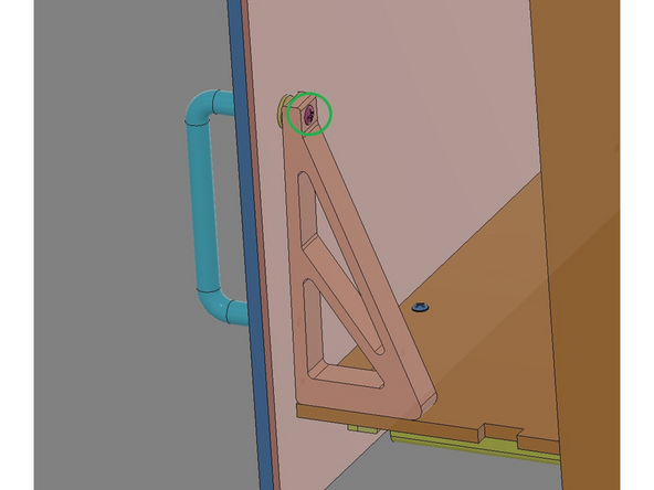
IMG 1 - If there is a 'tilt' in the Drawer Front Assembly, it can be adjusted to close the gap.
-
IMG 2 - Pull open the drawer and slowly tighten the screw at the top of the Alignment Bracket (highlighted in Green).
-
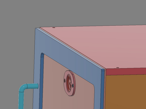
IMG 3 - Both sides might need adjustment, so alternate sides making small adjustments until the Drawer Front Assembly lays flush.
-
-
-
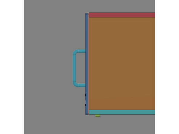
IMG 1 - If the Drawer Front Assembly isn't aligned with the Top, it can be adjusted.
-
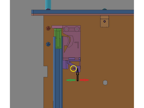
IMG 2 - The Glide Latches have an adjustment feature that slides back/forth to lift/lower the Drawer Front Assembly. To slide this feature, gently press the slide's adjustment arm inward (highlighted with the Black Arrow) and slide the feature towards the Glide Rail to lift it (Green Arrow) and away to lower it (Red Arrow).
-
IMG 3 - Make small adjustments to both sides to best level the Drawer Front Assembly.
-
-
-
Do Not Use Power Tools for assembly.
-
Some parts have been removed from these images to provide better visibility for these instructions. They DO NOT need to be remove to complete the assembly.
-
IMG 1 - Install the rear Exit Fitting into the Exit Panel.
-
IMG 2 - Insert the PTFE Tube through the rear Exit Fitting approximately 20"(~500mm). DO NOT tighten this fitting yet.
-
IMG 3 - Install and secure another Exit Fitting on the end of the PTFE Tube. This prevents snags and makes it easier to hold the PTFE when threading filament.
-
Once a spool of filament is loaded, the PTFE tubing length can be adjusted through the rear Exit Fitting.
-
-
-
Do Not Use Power Tools for assembly.
-
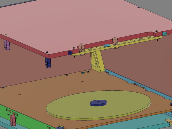
For these three images, the Rear Panel has been removed and replaced with an Acrylic Panel to help visualize how the PTFE tubing should be installed and how it will articulate when the tray is opened/closed.
-
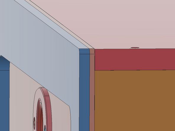
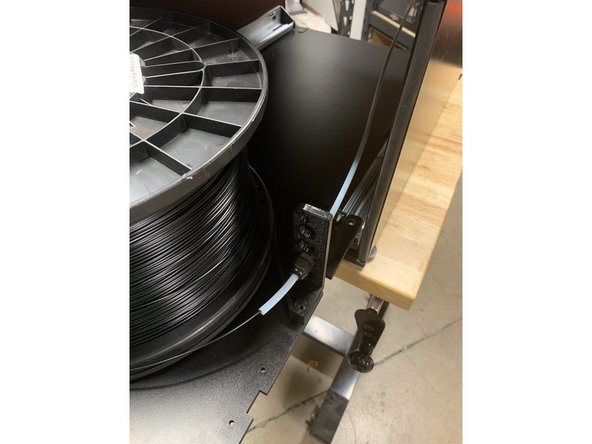
IMG 1 - Install x1 Exit Fitting into the Brake/Tower Assembly. Feed the PTFE Tube through the Exit Fitting leaving approx. 2-3 inches (50-75mm) sticking through towards the front. Tighten the Exit Fitting Cap to secure the tube.
-
IMG 1 cont. - Pull the Tray forward as far as it can travel . Tuck the remaining tube out the back of the cabinet.
-
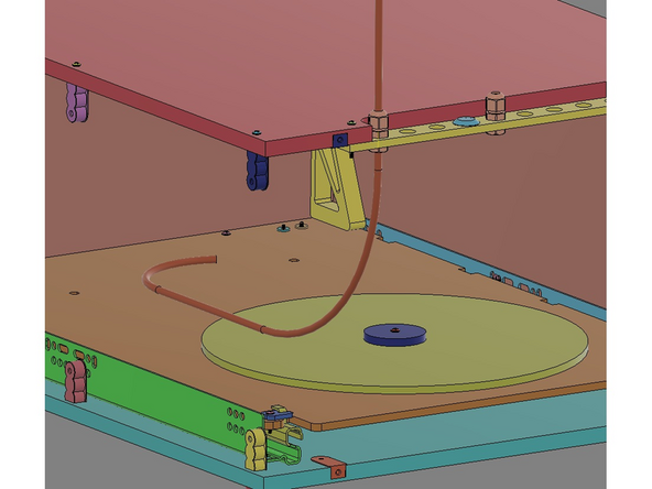
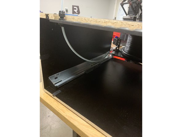
IMG 2 - Install x1 Exit Fitting into the Rear Exit Panel in the position shown. Feed the remaining PTFE Tube up through the Fitting leaving slack on the inside of the cabinet to provide free movement of the Tray and without any strain against the two Exit Fittings. Tighten the second Exit Fitting to secure the tubing.
-
The PTFE Tubing should have a natural curve from being coiled during shipping. Utilizes this natural curve when installing the tubing... curving "inward" towards the spool when passing though the front Exit Fitting (***IMG 1) and then "up & out" when passing though the rear Exit Fitting.
-
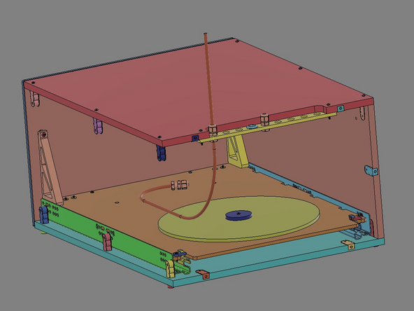
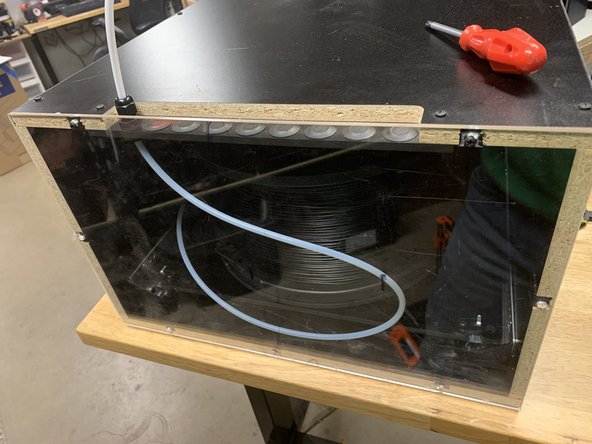
IMG 3 - Side the tray back into the cabinet to confirm smooth operation and that there is no strain is being applied to the two Exit Fittings.
-
The PTFE Tubing should dress/form-fit as shown.
-
-
-
Do Not Use Power Tools for assembly.
-
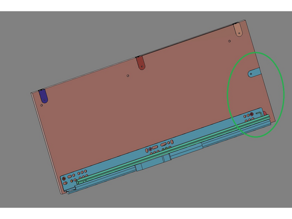
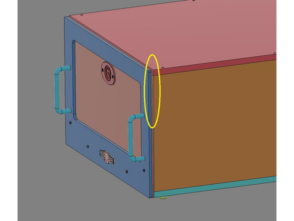
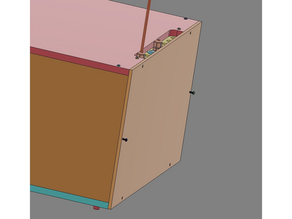
On v2.1, the Rear Panel installation is easier if the Tray Assembly is pulled forward.
-
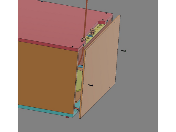
IMG 1 - Locate x6 16mm TF Screws and the Rear Panel. Align the Back Panel with the rear of the Main Assembly and insert two screws through the side holes and into the Butt Anchors (already installed in the Side Panels).
-
IMG 2 - DO NOT fully tighten these two screws yet.
-
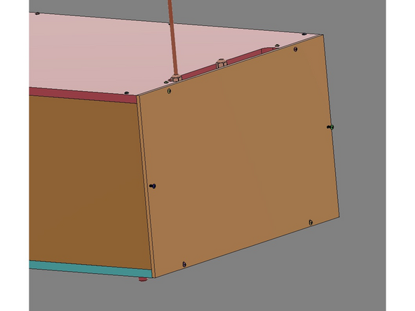
IMG 3 - Align the remaining four 16mm TF Screws into the remaining four holes in the Rear Panel. DO NOT fully tighten any of these screws until they are ALL fully engaged.
-
Slowly tighten each of the six screws.
-


Attached Documents
