Parts
No parts specified.
-
-
Do Not Use Power Tools for assembly.
-
IMG 1 - Locate the Latch Plate and x2 16mm TF Screws.
-
IMG 2 - The 16mm TF Screws will pass through the two empty holes at the center of the Front Exit Panel and into the Latch Plate
-
IMG 3 - Look inside the RepBox to ensure the Latch Plate is oriented properly.
-
-
-
IMG 1 - The Gasket Seal will need to be cut into four pieces; x2 Horizontal and x2 Vertical.
-
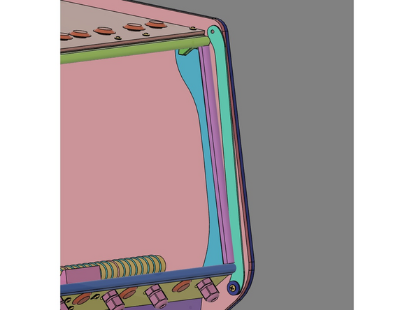
IMG 2 - This image shows the Top Seal installed.
-
IMG 3 - To determine the length of this Gasket Seal, use the RepBox as a guide. On the side without the Lid Prop, the gasket should be flush against the inside. On the side with the Lid Prop, it should flush against the Lid Prop minus ~1mm.
-
Repeat this process for the Lower Seal.
-
-
-
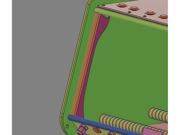
IMG 1 - This image shows one of the Vertical Seal installed.
-
The Vertical Seal should fit flush within the two Horizontal Seals.
-
IMG 2 - Repeat the process for the other Vertical Seal.
-
-
-
Do Not Use Power Tools for assembly.
-
IMG 1 - Locate x2 Flange Nuts, x1 Hygrometer, x1 Lid Trim Clamp and x2 16mm TF Screws.
-
IMG 2 - The Hygrometer is installed from the outside of the Lid Assembly. The Lid Trim Clamp then covers the Hygrometer. The 16mm TF Screws are inserted through Lid Trim Clamp and the Lid Assembly.
-
IMG 3 - Secure the 16mm TF Screws using the x2 Flange Nuts.
-
Do not over tighten these screws. They should be just tight enough to secure the Hygrometer from rotating.
-
-
-
Do Not Use Power Tools for assembly.
-
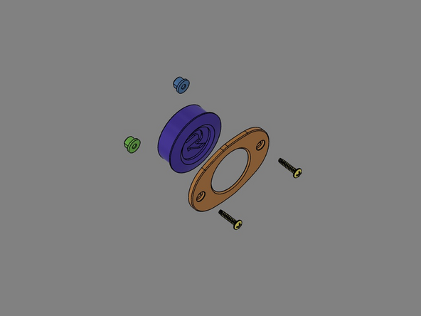
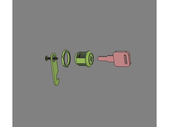
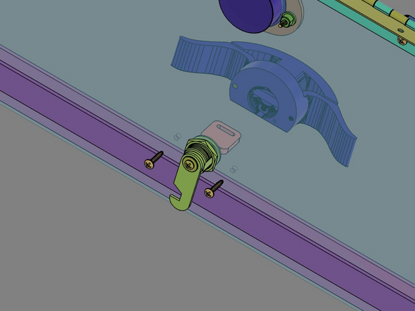
IMG 1 - Locate the Lockset hardware.
-
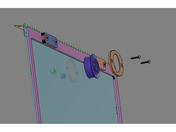
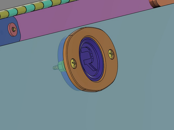
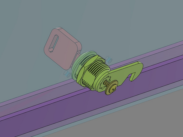
IMG 2 - Insert the Body of the Lockset through the hole in the Lid. Orient the Body so it aligns with the flat-side of the opening (as shown).
-
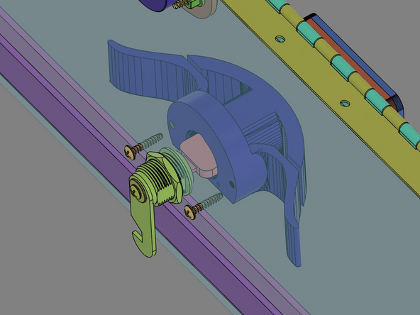
IMG 3 - From the inside of the Lid, install the Lockset Nut to secure the Body. Insert the Lockset key into the Body and rotate it clockwise until it stops.
-
IMG 3 cont. Install the Lockset Latch Plate (as show) and secure it with the Lockset Screw.
-
Verify the orientation of the Latch Plate and the Key (as shown).
-
-
-
Do Not Use Power Tools for assembly.
-
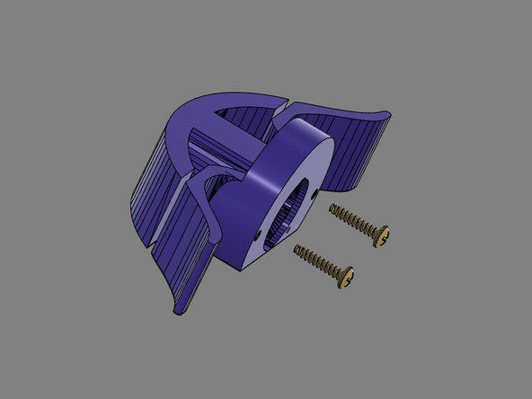
IMG 1 - Locate the Handle Set and x2 16mm TF Screws.
-
IMG 2 - Rotate the Lockset Key counter-clockwise until it stops. Verify the Key and Latch Plate are in the proper orientation (as shown).
-
IMG 3 - Slide the Handle Set onto the Key. The Handle Set should slide down the Key flush aginst the Acrylic Lid. Use the x2 16mm TF Screws to secure the Handle Set.
-
-
-
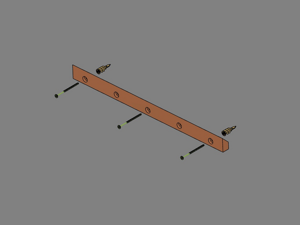
IMG 1 - Locate the French Cleat, x2 Wall Anchors and x3 3" Screws.
-
This hardware pack contains x1 spare Wall Anchor.
-
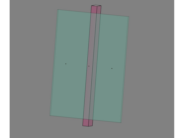
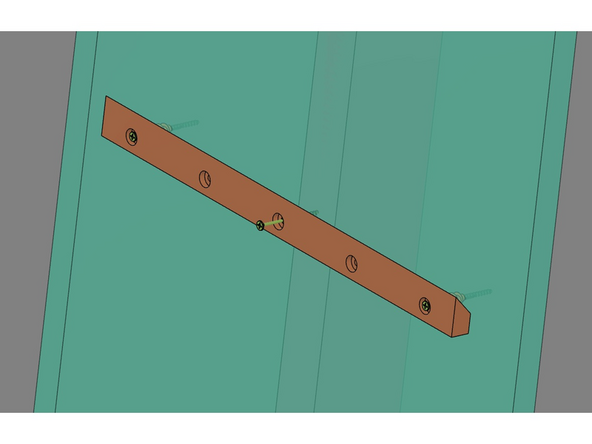
IMG 2 - Identify a location that has at least one stud. It is preferred to locate the French Cleat so it is centered on the stud.
-
The outer holes of the French Cleat are spaced apart 16" on center, so it is possible to mount the French Cleat to two studs (one on each end). This is best if possible.
-
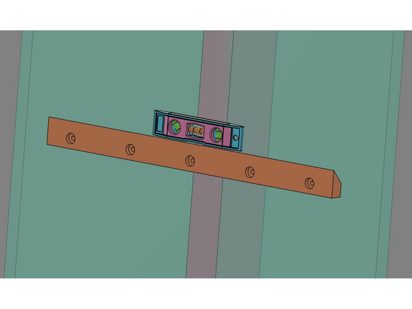
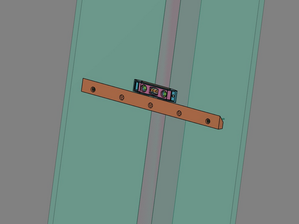
IMG 3 - Use the French Cleat to pre-mark the wall for the next step.
-
Please use a level to unsure the French Cleat is level before making these pre-marks.
-
-
-
Do Not Use Power Tools for assembly.
-
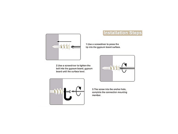
IMG 1 - Please read and follow these instructions for installing the Wall Anchors.
-
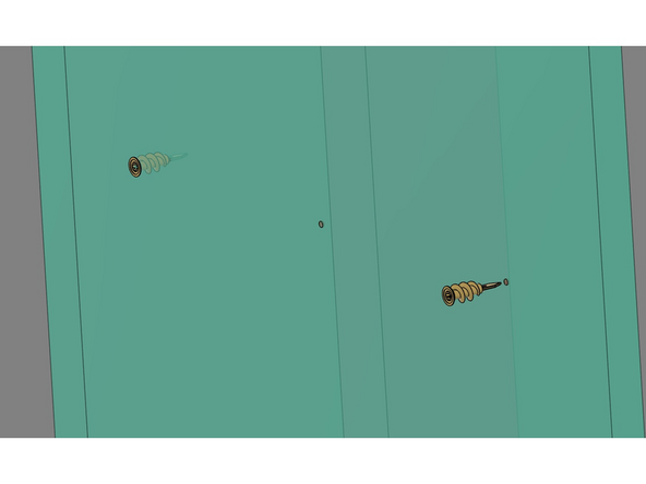
IMG 2 - Install the x2 Wall Anchors into the pre-marks made in the previous step.
-
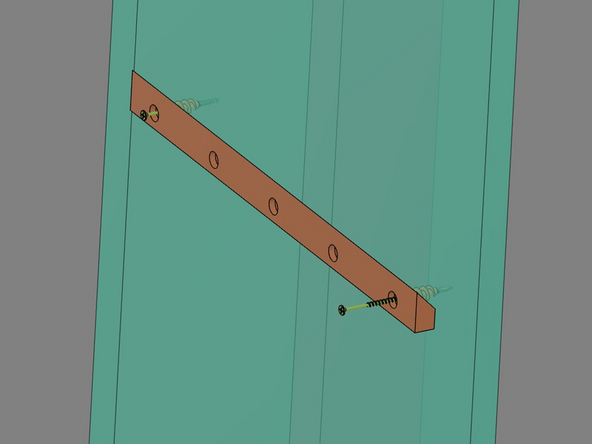
IMG 3 - Align the French Cleat with Wall Anchors and install the 3" Screws.
-
Do not fully tighten these screws yet. Bring them down flush
-
-
-
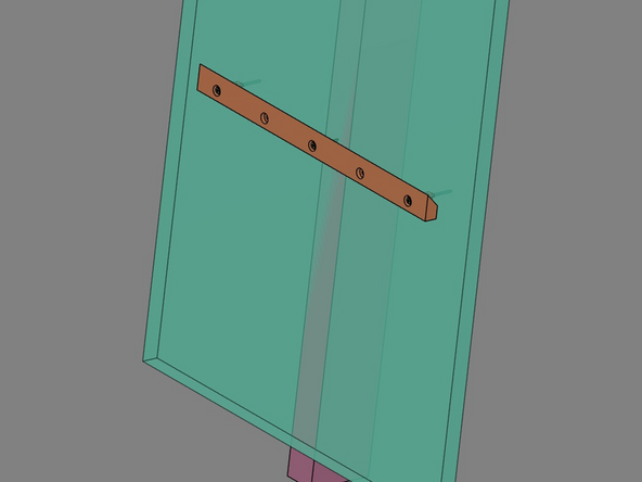
IMG 1 - Re-level the French Cleat and secure the screws into the Wall Anchors.
-
Make sure the French Cleat is level before moving to the next step.
-
If you would like to pre-drill a hole for the 3" Screw going into the stud(s), please do this now. This hole should be no larger that 7/64th (2.5mm).
-
IMG 2 - Insert the 3" Screw through the French Cleat and into the stud, then secure it.
-
-
-
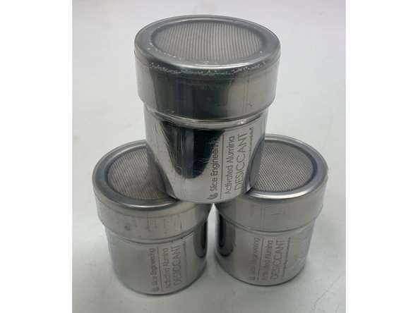
These desiccant canisters can be inserted directly into the filament spools before loading them intothe RepBox OR they can be placed inside the front exit panel laying on their side.
-