
Parts
No parts specified.
-
-
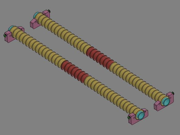
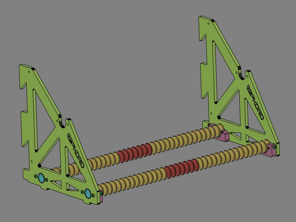
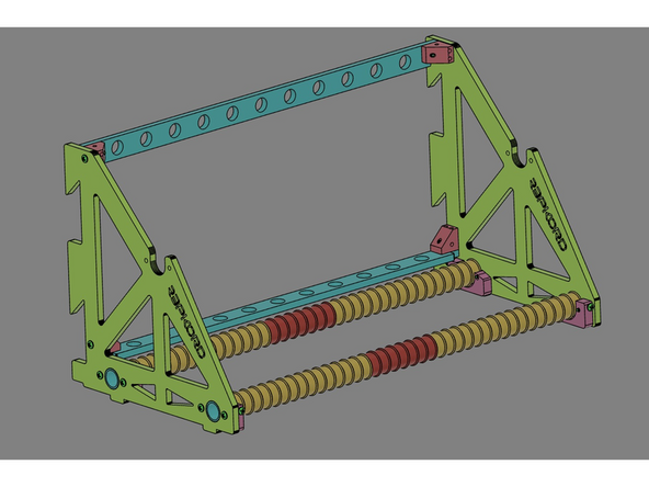
IMG 1 - This is the completed rack assembly (side/front view).
-
IMG 2 - This is the completed rack assembly (side/back view).
-
-
-
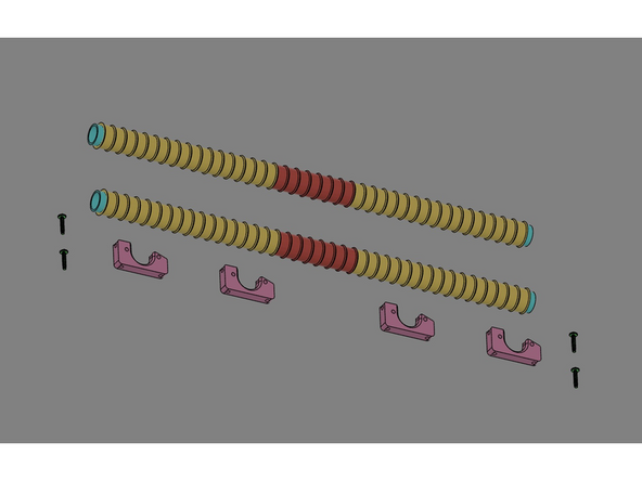
IMG 1 - The laser cut parts panel containing x2 Rack Sides and x2 Cross Rails.
-
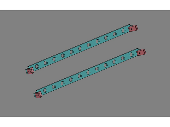
IMG 2 - x2 Glide Rail Assemblies.
-
IMG 3 - x4 Rod Clamps, x4 Corner Brackets, x5 Exit Fittings and x20 16mm TF Screws.
-
-
-
Do Not Use Power Tools for assembly.
-
IMG 1 - Located the Glide Rails, x4 Rod Clamps and x4 16mm TF Screws.
-
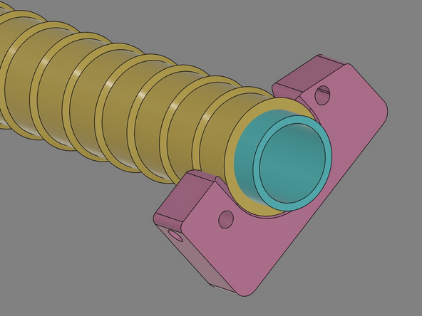
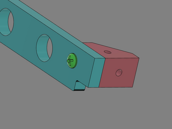
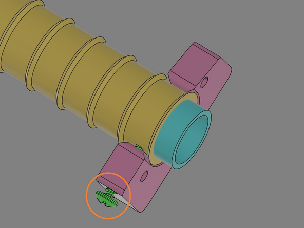
IMG 2 - Slide one of the Rod Clamps" onto one of the Glide Rails. The Rod Clamp will have light press fit onto the Glide Rail''.
-
IMG 2 cont. - The protruding chamfer on the glide will fit into the recessed chamfer in the Rod Clamp.
-
IMG 3 - Install a 16mm TF Screw into the Rod Clamp. Carefully thread this screw into the Glide just tight enough to hold the Rod Clamp to the Glide Rail. In a later step, some final adjustments will be made before securing the 16mm TF Screw.
-
-
-
Do Not Use Power Tools for assembly.
-
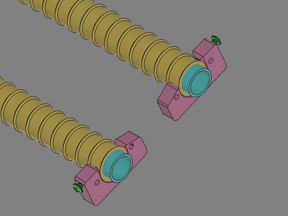
IMG 1 - Repeat the process and install a second Rod Clamp and 16mm TF Screw to the other Glide Rail.
-
NOTE how this second Rod Clamp is oriented differently from the first one. Confirm their orientations before continuing.
-
IMG 2 - Repeat this process again with the remaining x2 Rod Clamps on the far ends on the Glide Rails.
-
NOTE - Confirm that the orientations of all Rod Clamps are correct per IMG 2.
-
-
-
Do Not Use Power Tools for assembly.
-
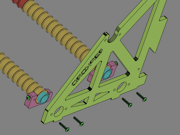
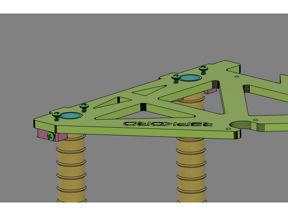
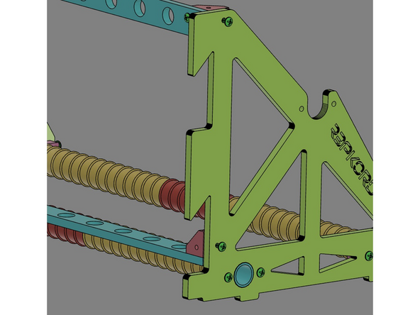
IMG 1 - The metal tubes inside the Glide Rails will index into the large circular openings of the Racks.
-
Note the orientations of the of the Rod Clamps. They must be orientated as shown.
-
IMG 2 - Locate x2 16mm TF Screws. Insert the Glide Rail into the Rack and secure them together with the screws that pass though the Rack and into the Rod Clamp. Seat these screws firmly.
-
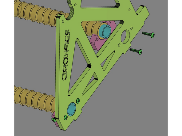
IMG 3 - Repeat the process with the second Glide Rail.
-
-
-
Do Not Use Power Tools for assembly.
-
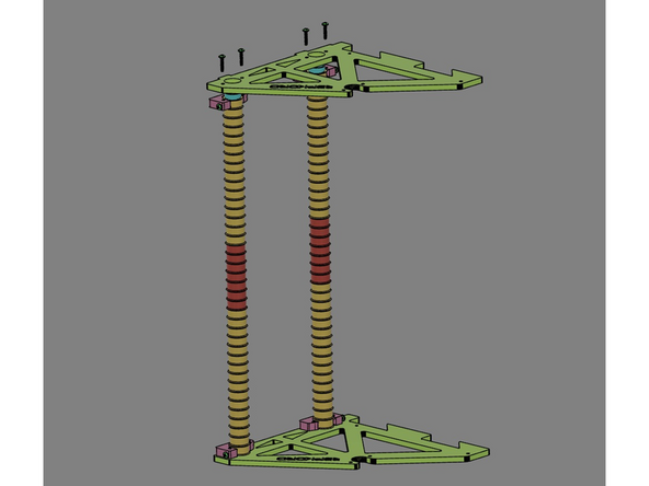
IMG 1 - Adding the second Rack is similar to the previous step, but the Rack will connected to the Glide Rails simultaneously.
-
Standing the assembly up-right makes this step easier.
-
IMG 2 - Locate x4 16mm TF Screws. Lower the Rack down onto the Glide rails, insert the screws through the Rack and into the Rod Clamps.
-
Start each screw as it's inserted but don't tighten them all the way until all four screws are started. Then secure them all firmly.
-
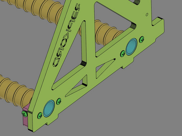
IMG 3 - Set the assembly down flat on your work surface with the Glide Rails down (as shown).
-
-
-
Do Not Use Power Tools for assembly.
-
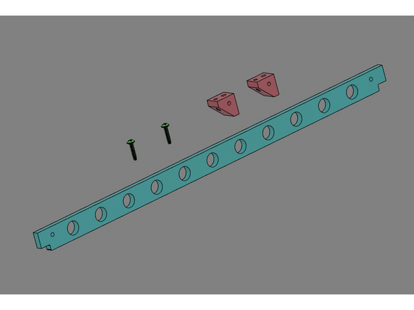
IMG 1 - Locate one of the Rails, x2 16mm TF Screws and x2 Brackets.
-
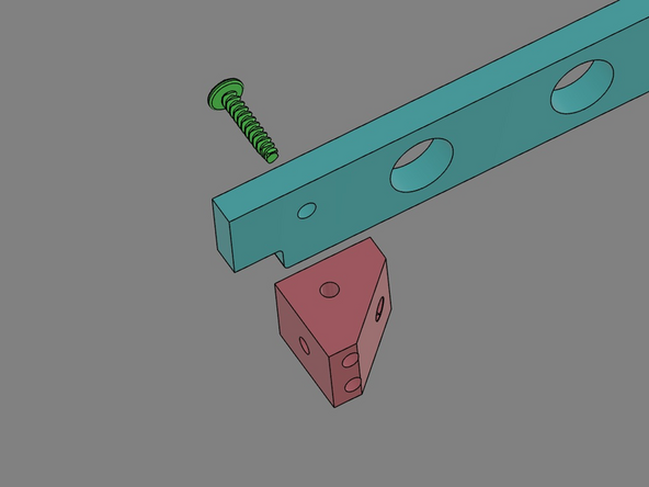
IMG 2 - On one end of the Rail align one 16mm TF Screw and Bracket as shown. The screw will pass through the Rail and into the Bracket to secure it firmly.
-
Confirm that the Rail and Bracket are oriented correctly.
-
IMG 3 - This is a view from the back side to provide an alternate view to help confirm the assembly orientation.
-
Repeat this process for the other end of the Rail.
-
-
-
Do Not Use Power Tools for assembly.
-
IMG 1 - Assembly the second Rail just like the first one.
-
Confirm the Rails have the same assembly/component orientations.
-
-
-
Do Not Use Power Tools for assembly.
-
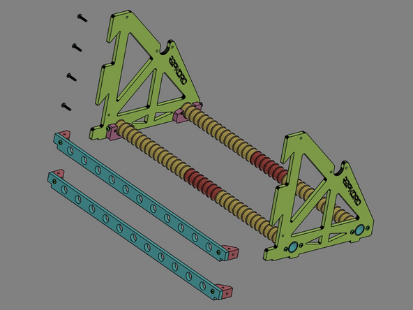
IMG 1 - Locate the last four 16mm TF Screws.
-
IMG 2 - The Rails will be installed between the two Racks. Their orientation will be similar with the top Rail vertical while the lower Rail will be rotated to be horizontal.
-
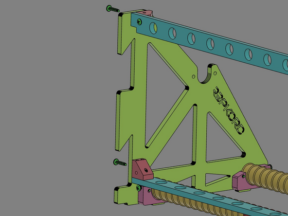
IMG 3 - Insert the screws though the Racks into the Brackets. Once all four screws are started, then tighten them to secure the Rails as shown.
-
-
-
Do Not Use Power Tools for assembly.
-
IMG 2 - Set the finished Rack on the flat work surface (as shown). Check to see if the Rack is setting flat without any twist.
-
If it doesn't sit flat, loosen the four screw in the Rod Clamps and gently adjust the assembly to remove the twist.
-
This would all be a good time to remove any excessive air gaps in the assembly. Gently compress the assembly by applying inward pressure to both Racks simultaneously.
-
Once everything is flat and adjusted, slowly tighten the four screw in the Rod Clamps. Don't over-tighten them, just bring them down to a firm set.
-
Complete the Rack by re-checking tightness of all other screws in the assembly.
-
-
-
Do Not Use Power Tools for assembly.
-
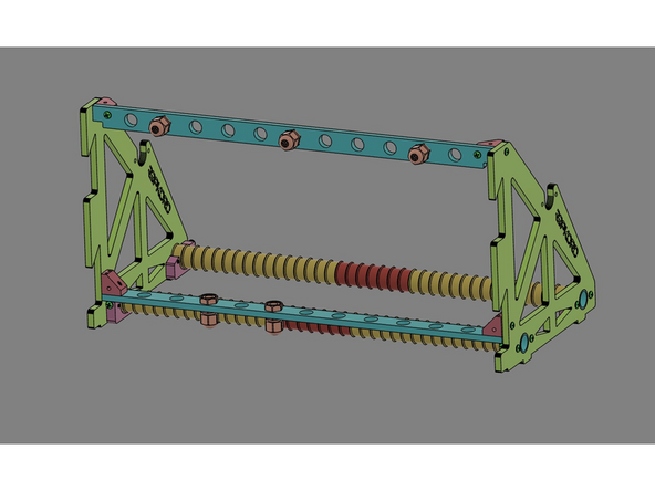
IMG 1 - There are six Exit Fittings included with the kit. They should be located as needed. If printing from inside the TurnTable:Filament Filing Cabinet, the Exit Plugs should be on the top Rail. If the Rack is being wall mounted, the Exit Fittings should be on the lower Rail.
-


Cancel: I did not complete this guide.
One other person completed this guide.