Difficulty
Easy
Steps
23
Time Required
- 2: Main Assembly 23 steps

In Progress
This guide is currently being written. Reload periodically to see the latest changes.
Quiz
0
-
-
Your kit includes anti-skid feet as shown here. Open the package up and DISCARD the screws that were included with it. You will NOT be using these.
-
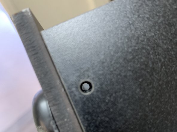
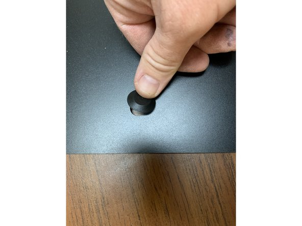
Take a 16mm TF screw from the fastener bag and press it through the hole in a foot so the screw head is on the inside of the recessed hole, resting against the metal washer.
-
Repeat for the remaining feet.
-
-
-
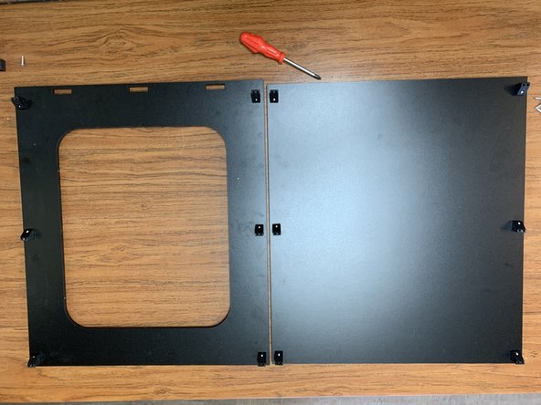
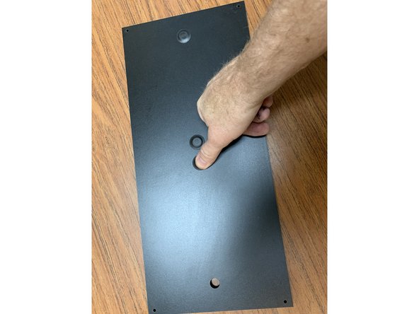
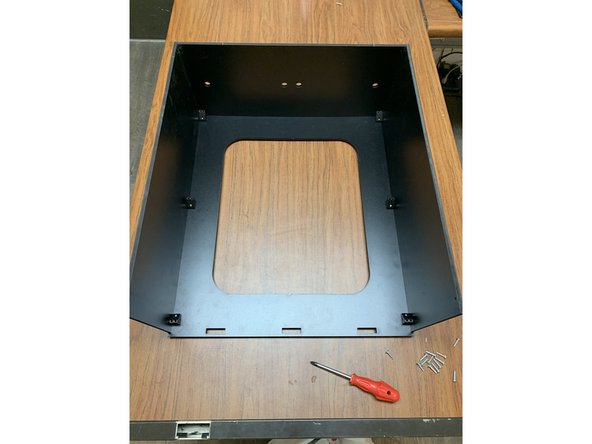
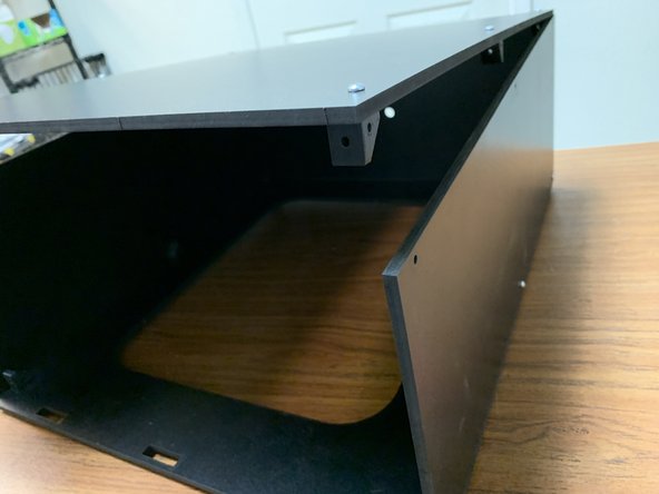
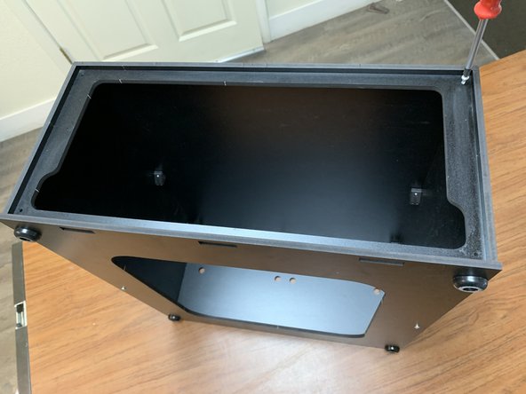
Grab the Base Panel (Part 3) and align it so that the three rectangular notches are facing you. This side is the front of the box. (Picture 1 shows the base panel upside-down.)
-
Inspect one of the 3D-printed brackets. Note that the hole positions are different and their orientation will matter for correct assembly.
-
The corner of the bracket with two holes in it will always face up towards the top of the box for all brackets on the base panel. When installed correctly each of the brackets will be oriented as shown in picture 2.
-
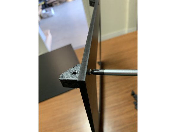
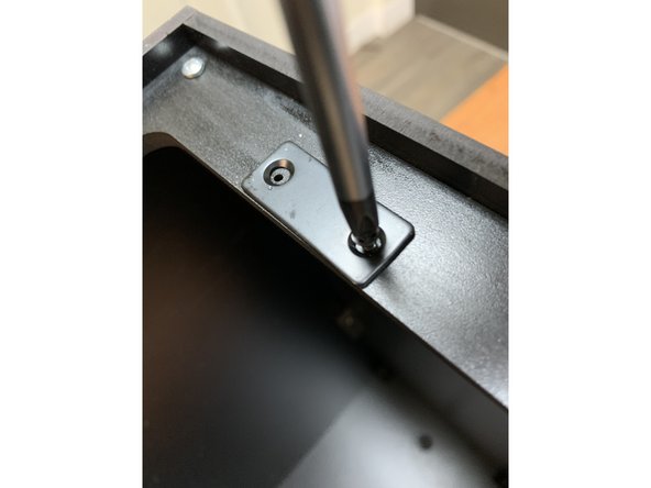
CAUTION: It may appear that there are two holes on the face you're tapping into on the printed part but only one of them is a straight through hole and its the one closer to the edge corner of the bracket. The other is angled at 45 degrees. Make sure you're tapping into the correct hole.
-
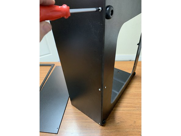
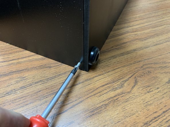
Using a #2 Phillips-head screwdriver, thread the screw and foot through the base panel and fasten on the opposite side with one of the 3D-printed brackets. The screw will self tap directly into the 3D-printed bracket.
-
Repeat this process for the remaining feet, ending up with one at each of the four corners of the box.
-
For the brackets in the center of each side of the base, simply fasten with a single screw. No foot is required in this location.
-
See the next step for more details about bracket orientation.
-
-
-
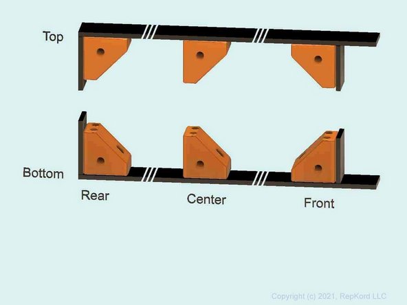
All brackets built so far should have the corner with two holes pointing upward toward the top of the box.
-
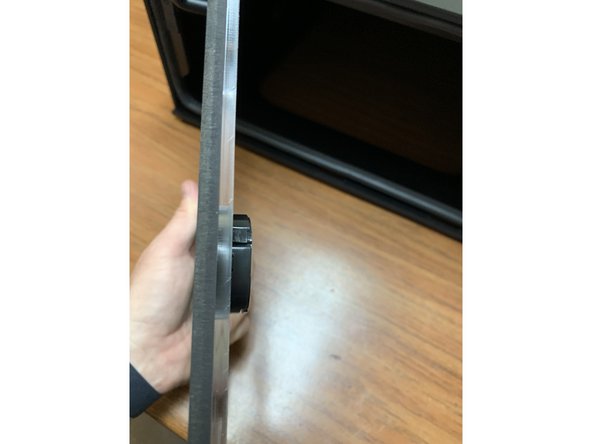
A side view is provided here. (It also shows the Top panel brackets, which you will assemble later.)
-
For the front brackets, the angled face points towards back of the box.
-
For the rear and center brackets, the angled face points towards the front of the box.
-
-
-
Grab the Top Panel (Part 1) in order to attach the six (or seven for the XL version) brackets, similarly to how you built out the Bottom Panel.
-
For each bracket, pass a 16mm TF screw through the hole in the top panel, and self-tap it into a bracket on the opposing side. When properly installed, each bracket's double-hole side will point down towards the base.
-
See the prior step for orientation of the angled faces.
-
Make sure all 12 (or 13 for XL) brackets are attached and oriented as shown in picture 2. Once complete, move on to the next step to add the side panels.
-
-
-
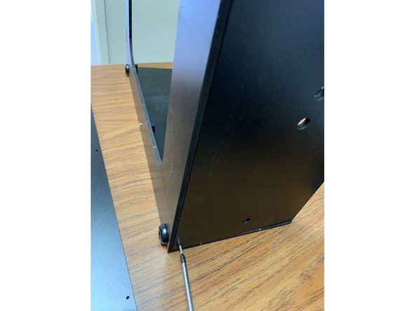
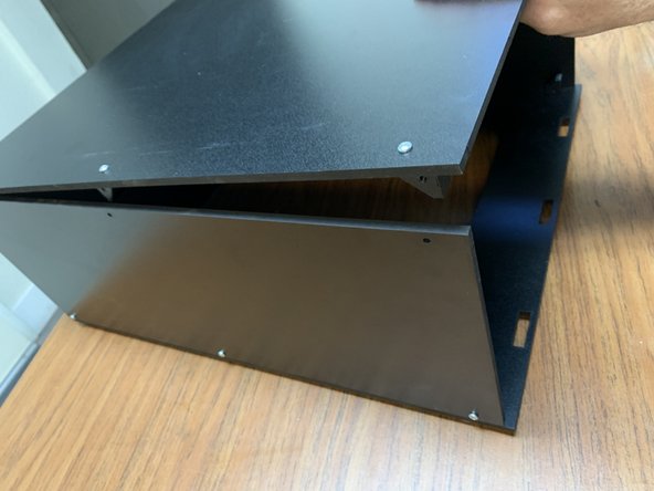
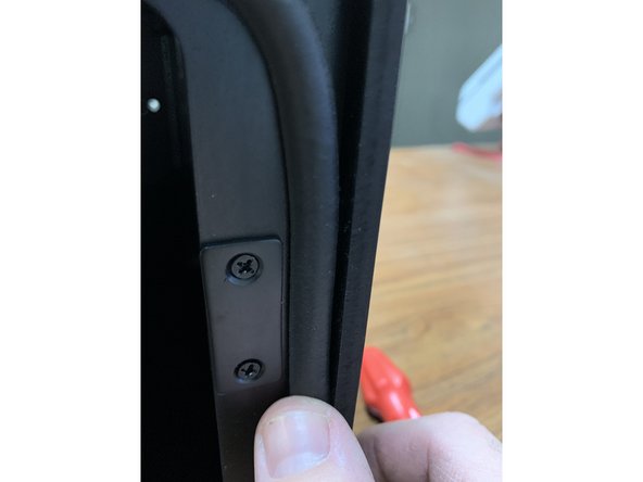
Grab one of your two side panels (Part 2) and lay it onto your Base panel assembly as shown in picture 1.
-
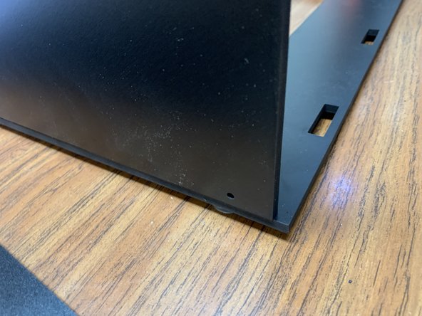
Each side panel will line up flush with the rear but won't extend all the way to the front. THIS IS NORMAL. Verify proper panel orientation by looking through the holes. They should line up with bracket side holes as shown in picture 2. If they don't line up, flip the panel around. The holes on one end are slightly closer to the edge.
-
Once you've verified the panel is oriented properly, fasten it to the base assembly's brackets using 3 TF screws as shown.
-
-
-
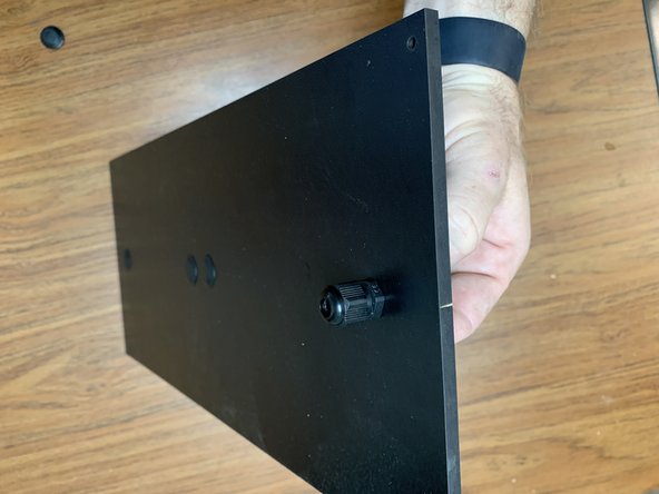
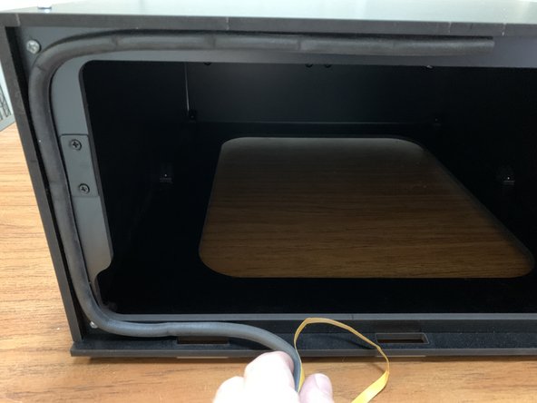
Locate the Rear Panel (Part 4). We'll start by prepping it with its plugs and fittings before we attach it to the box. You can certainly adjust this later but we find it easier to prep for the default setup at this point.
-
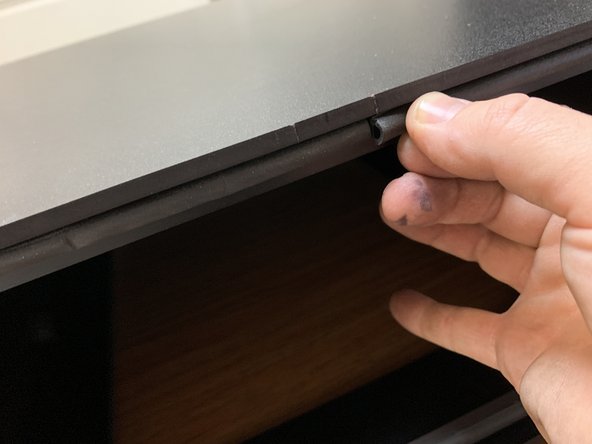
Remove three Exit Plugs (Part 14) from the Parts Pack and press them into three of the four holes in the rear panel, leaving one closest to the edge open for our Exit Fitting.
-
Remove the Exit Fitting (Part 25) from Parts Pack C and remove the end nut. Slip the fitting through the Rear Panel's remaining open hole and fasten it with the nut on the opposite side of the panel as shown in picture 3.
-
Note: If the holes on your rear panel are offset to one side we recommend orienting closer to the bottom of the box. Should you choose to use the optional quad spool kit in the future this will make the rear spools line up a bit better with the PTFE Guide Tube.
-
-
-
Using two TF screws, fasten the Rear Panel to the base assembly as shown.
-
As mentioned in the earlier prep step, double check the orientation of the rear panel. If the rear panel holes are offset from center, attach the panel so that the holes are nearer to the base.
-
Attach the remaining side panel to the base assembly with three TF screws as shown. Make sure the back edge lines up with the back edge of the base panel. When correctly installed it should look like picture 3.
-
-
-
Orient the top panel assembly so the holes on the sides of the brackets line up with the holes at the top of your side and rear panels.
-
Once you've verified the alignment, fasten the side panels to the Top Panel assembly brackets with a TF screw through each of the open Side Panel holes.
-
-
-
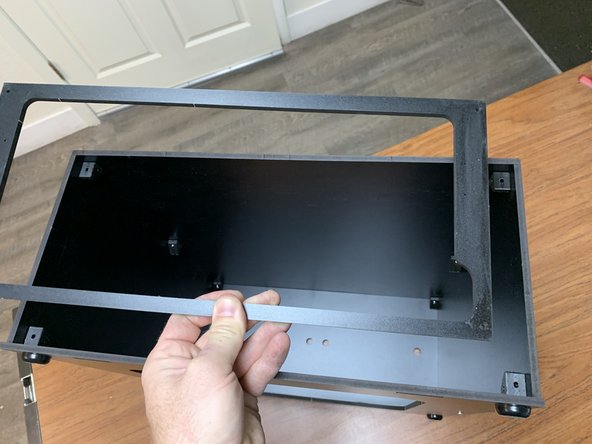
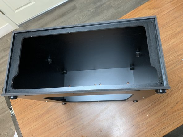
Locate the front Seal Flange (Part 5) and orient your assembly to install it to the face of the box as shown in picture 1.
-
Note: When properly oriented, the thin edge of the Seal Flange will be nearer the base of the box.
-
Fasten the Seal Flange to the four exposed brackets with TF screws.
-
-
-
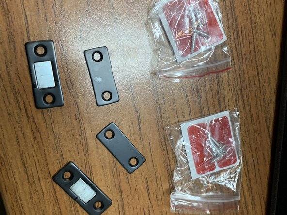
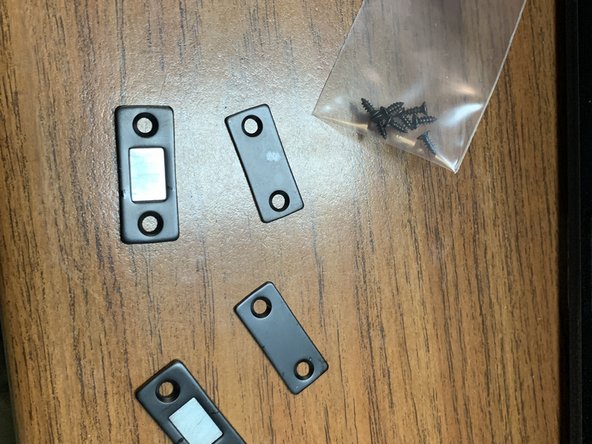
Grab the Mag Catch set (Part 15) from the parts pack.
-
Remove the magnets and catch plates for now, but set aside the adhesive strips and included screws for the time being.
-
Select four of the M3x6mm wood screws from the parts pack.
-
-
-
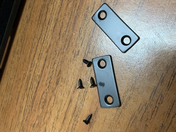
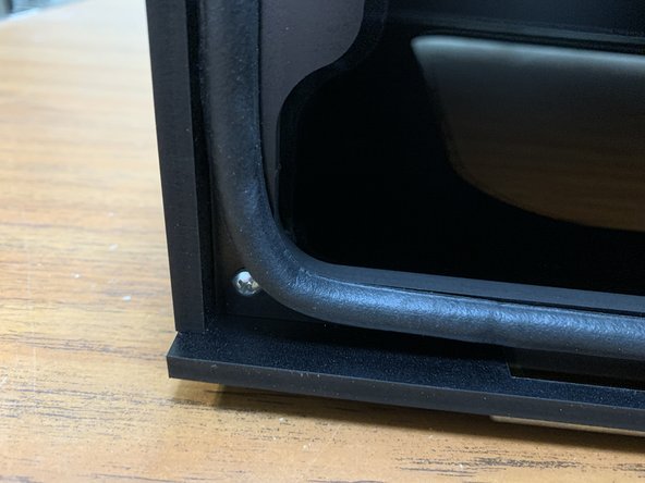
Using the M3x6mm wood screws, fasten the mag catches to the seal flange at the pre-drilled holes as shown here. You will fasten two screws into each catch plate.
-
Even though the mag catch holes accept beveled screw heads, the M3x6mm wood screws are round-head. This is normal and expected.
-
Leave these screws slightly loose to start. They should be tightened so they're flush with the top of the catch plate but not completely bottomed out. This allows for better catchment of the magnet when you clip the door on.
-
Leaving the catch plate screws loose is more critical when the Seal Gasket (assembled later) is brand new. As the gasket compresses over time, you can tighten these screws as needed to increase seal pressure.
-
-
-
Please read these critical alignment tips PRIOR to installing the Seal Gasket on the Seal Flang so you know exactly how you want it to align. Details of the actual installation are on the following step.
-
The position of the Seal Gasket will dictate how cleanly and evenly the seal on the lid happens, and how well the lid will latch. If you're having issues getting the lid to latch, make sure your Seal Gasket is installed properly.
-
There are three notches along the base at the box's front. The seal gasket should be lined up AS FAR from those notches as possible, at the top edge of the seal flange. This will allow you to more easily put the lid in place.
-
The seal gasket at the edges should be as far away from the Mag Catches as possible, and pressed to the side edges as close to the side panels as possible. This will allow for a cleaner mating between the magnets on the lid and the Mag Catches.
-
-
-
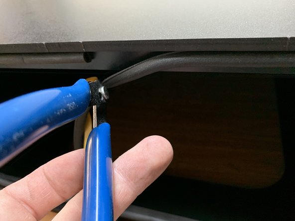
Remove the backing from the seal gasket and start pressing the Seal Gasket (Part 21) around the face of the Seal Flange. Start at the top center of the Seal Flange.
-
As you round the corners be sure to create a long enough radius to avoid touching the top of the TF screw but not so sharp that it creases or bunches up.
-
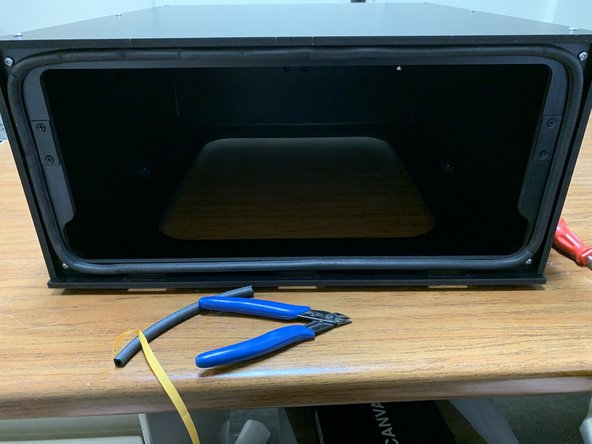
Cut any excess seal gasket with scissors or flush cutters so the gasket lines up with the starting edge at the top center of the Seal Flange where you started.
-
-
-
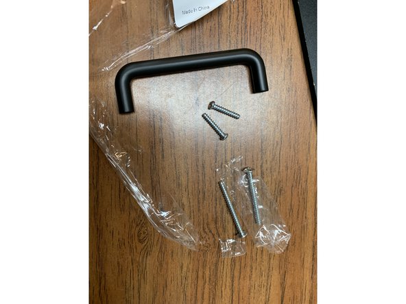
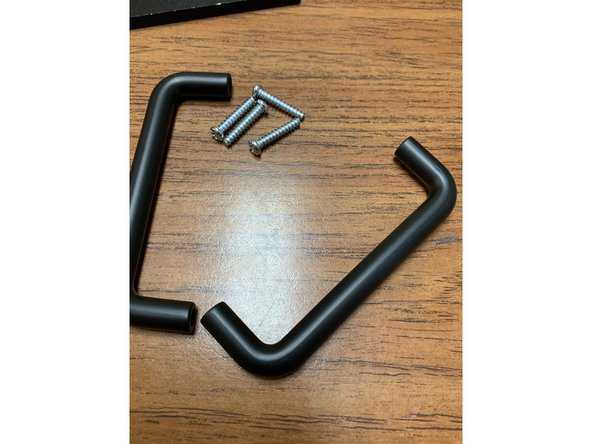
Locate the two Lid Handles (Part 13) and open up the included screws. Discard both of the LONGER screws. They will not be needed.
-
Prep both sets as pictured. We'll be using these screws to prep the rest of the lid in the next step.
-
-
-
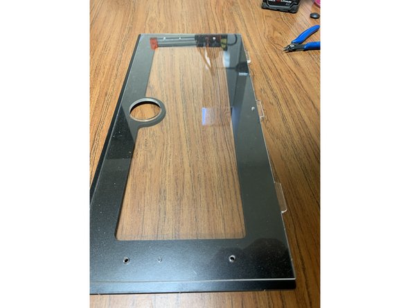
Prep your acrylic panel by first removing the clear protective film from BOTH SIDES.
-
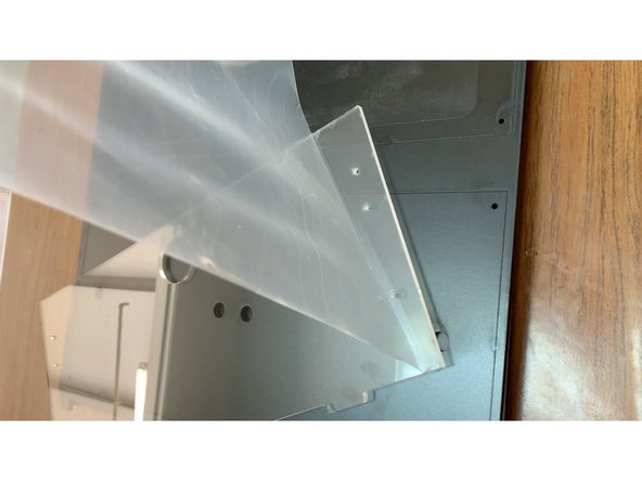
Align the Acrylic Lid (Part 12) with the Faceplate (Part 11) so the holes for the handle line up as shown.
-
Lay the Mag Catch magnetic sides (the other side of Part 15 from earlier) atop the acrylic as shown in picture 3 and press in the two shorter handle screws from the previous step on each side to line everything up.
-
When lined up properly the hole for the hygrometer should be centered in the corresponding hole in the faceplate. The edges of the acrylic on the top and sides will be recessed from the edges of the faceplate but the bottom tabs will overhang. This is normal.
-
-
-
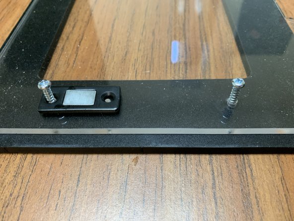
Gently lift the lined up lid assembly from the previous step and line up the handle with the screw holes on the back side. Tighten the screws into the handle as shown in picture 2.
-
Using two of the remaining M3 x 6mm wood screws, one on each of the left and right sides of the lid, fasten the Magnet Catches. The screw goes from the interior through the Mag Catch and Acrylic Lid, and bites into the Faceplate as shown. Do not overtighten, or you will risk stripping the Faceplate material.
-
-
-
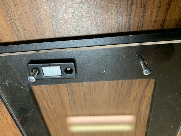
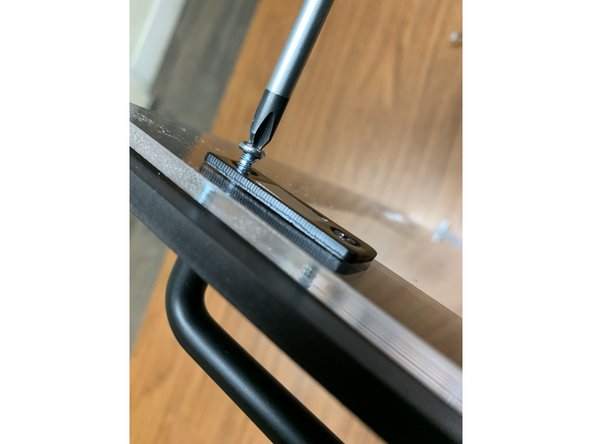
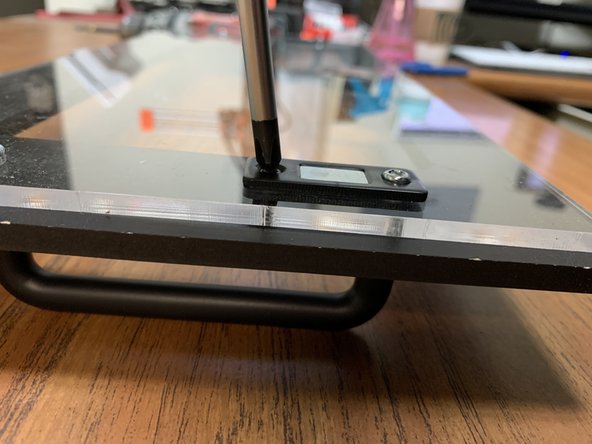
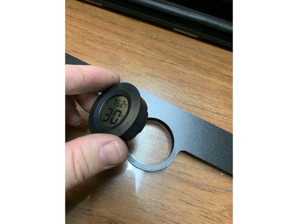
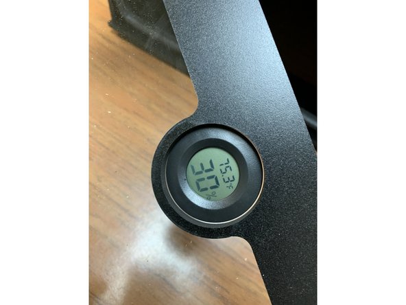
GENTLY press in the hygrometer into the acrylic lid/faceplate assembly as shown.
-
You may need to compress the tabs at the side of the hygrometer slightly and rotate back and forth to press it into the acrylic. It should be a snug fit.
-
-
-
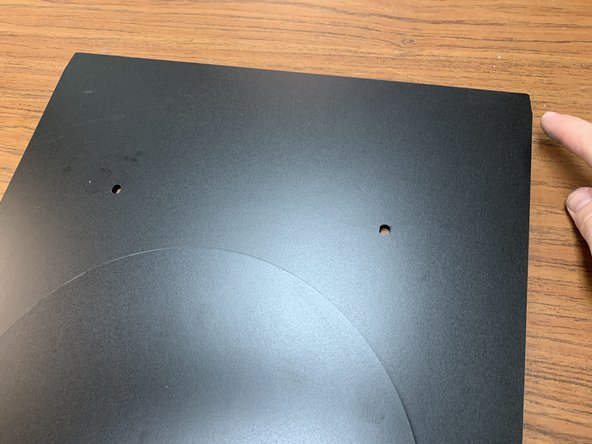
Locate the Tray (Part 6) from the cut panel set. The back of the tray will have slightly tapered ends as shown in picture 1.
-
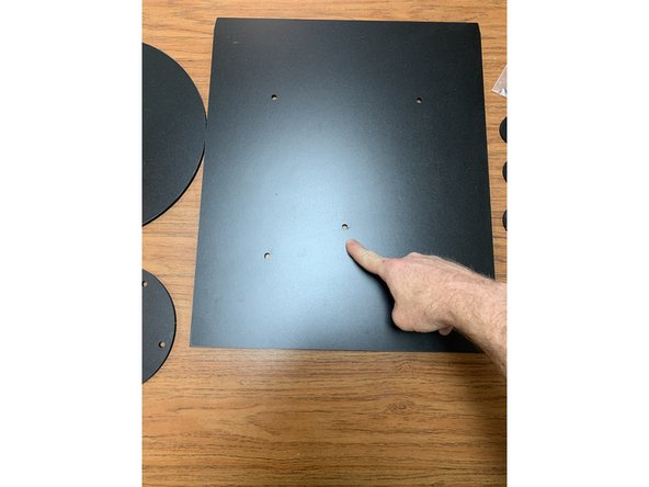
There are multiple holes in the base of the tray for optional turntable configurations. The default configuration uses the center hole thats offset towards the front of the tray. This is normal and makes the turntable more easily accessible when assembled.
-
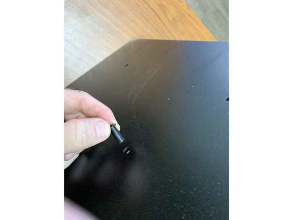
Locate the 3D-printed hub axle (Part 20) and press it through the center hole as shown. Hold it in place with a finger as you flip it over and lay it on a table to keep it in place. See the following video for more detail.
-
-
-
Place the 3D-printed Hub Axle into the Tray and flip it over onto a table as shown.
-
-
-
WARNING: DO NOT OVER TIGHTEN THE HUB. Doing so can crack the printed part easily. If you accidentally do so you can easily print another part from the available 3D-printed part files.
-
Assemble the turntable tray as shown. Note the difference between the two keyed Base Hubs (Part 9), The Thinner Base Hub Spacer, and the Top Hub (Part 10).
-
Start by placing the 3D-printed hub in the base tray. Notice there are multiple hub position options on your tray. For a single large spool we recommend the center hole closest to the front of the tray but you may choose whatever is most convenient for your desired configuration.
-
Lay the two base hubs with the base spacer in between over the printed hub as shown.
-
Lay the Bearing Race (Part 7) over top the base hub assembly using five 7mm bearings (Part 18) from the parts pack as shown.
-
Place the turntable atop the bearing race and around the base hub assembly as shown. If the hub assembly is done correctly the top of the hub should be slightly higher than the height of the race with the turntable on top of it.
-
Screw the hub cap to the top of the base hub assembly. Each Turntable set comes with two options for top hub caps. Choose the one that best fits the spools you're looking to use with the kit. The larger of the two works well with more common 2 inch arbor spools while the smaller is designed to accommodate large 5kg spools.
-
-
-
Insert the tray assembly and attach the front lid as shown.
-
When attaching the lid angle it 45 degrees away from the top of the box to line up the lid tabs and avoid dragging the seal gasket down into the lid tabs and then tip the front forward until the magnets engage.
-
-
-
Lay your filament onto the turntable tray and feed the filament through the PTFE guide tube and off to your 3D printer! That's it! You made it!
-