
Difficulty
Moderate
Steps
13
Time Required
- 0: v2.25 Unboxing and Preparation 13 steps

In Progress
This guide is currently being written. Reload periodically to see the latest changes.

User-Contributed Guide
This guide is not managed by the site's staff.
Introduction
This guide helps walk you through the unboxing and preparation of parts for making the RepBox v2.2.
This document and the subsequent assembly guide work really well in combination with the existing, published videos.
-
-
When you get your Repkord v2.2 Repbox, it will come with a set of "panel sheets", some tubes containing parts, and a bag of 3D-printed pieces.
-
To prepare for assembly, you should identify the main parts, and have a firm, clear work area ready. We recommend working on a desktop or work table. There are parts that may have black edges (laser-cut MDF pieces) or a small amount of excess grease (608 bearings) that can get your work surface dirty.
-
The panel sheets are made of MDF or acrylic. They are bundled with a thin plastic (styrene) sheet of parts, and the clear acrylic lid. All that is wrapped in shrinkwrap plastic, so you can remove that carefully now. You will break the pieces out of the sheets in a later step.
-
The tubes contain hardware pieces, such as hinge pieces, screws, hole plugs, and filament glands.
-
-
-
The MDF panel parts are shipped with white on one side, and black on the other. For this assembly guide, the build will be done with white on the exterior, mostly. However, you may opt to switch things around since many pieces are symmetrical and/or reversible.
-
If you bought the acrylic version of the RepBox, just follow along based on the shapes shown. One extra piece of preparation for acrylic parts is that you have to remove protective film from both sides of each part before putting the part onto the box.
-
The panel parts are held to panel sheets by tabs, small bits that were left uncut during the laser cutting process. You will need to separate the parts from the sheets by cutting or snapping the tabs.
-
The following steps will show examples of panel separation, along with part labeling. Later, you will see the parts laid out in order of part number, and then roughly in order of assembly.
-
As you go about separating the panel parts, you might want to label them, too. It may be ok to use something like sticky memo notes to do this. The images shown here use a different labeling mechanism that worked on MDF, but may not do well for acrylic.
-
-
-
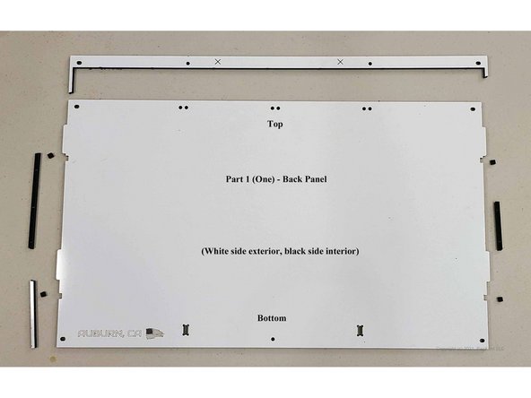
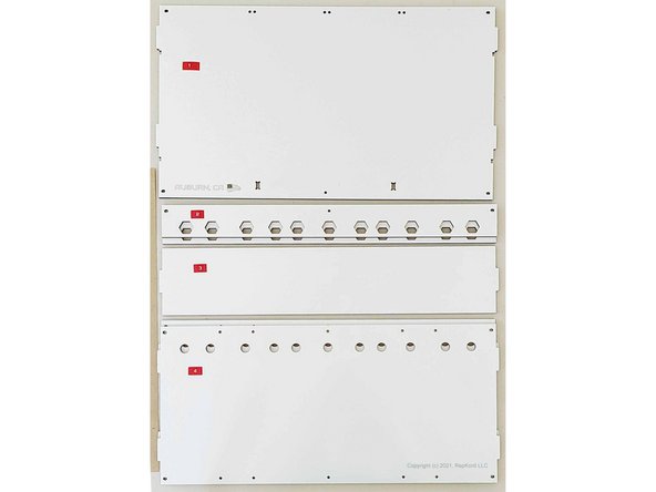
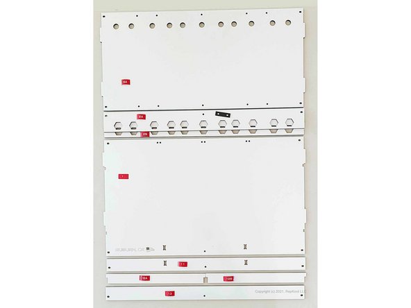
Panel part 1 is the back (or rear) panel. It's large, and nearly takes up the whole sheet.
-
For this and subsequent images, click on the image to scale it up to full size in order to see details.
-
-
-
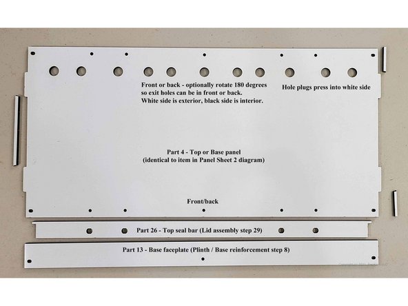
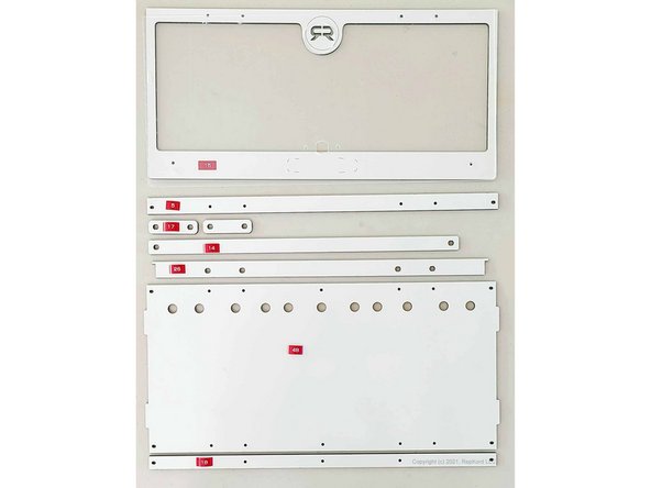
Another panel holds panel parts 4, 26, and 13. There are actually two panel parts 4, and one of them is on another panel sheet. One serves as the box top, and the other as the box base. It's the big rectangle here with 11 large exit holes, tabs on both ends, and 7 screw holes at the front and back.
-
Part 26 is the Top Seal Bar. It's the one with two little sticks pointing out at the ends, and four medium-sized oblong holes.
-
Part 13 is the Base Faceplate. It's a long rectangle with three holes, two of them oblong at the ends, and one circular hole in the middle.
-
-
-
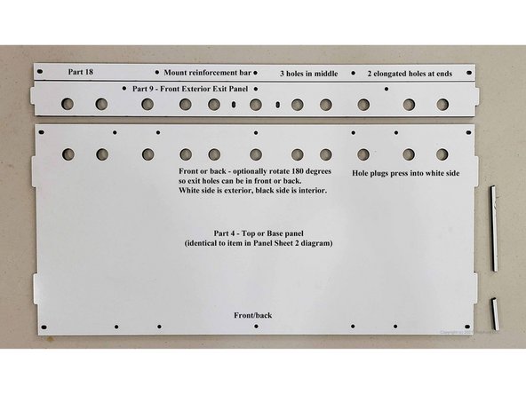
Another panel contains parts 18, 9, and the second of the part 4 pieces. As mentioned in the prior step, part 4 is for either the box top or bottom.
-
Part 18 is the Mount Reinforcement Bar. It is long and skinny with two elongated holes at the end, and three circular ones in the middle.
-
Part 9 is the Front Exterior Exit Panel. It is long with tabs on the ends, 11 large round holes, two elongate holes near the middle, and three circular holes along one edge.
-
-
-
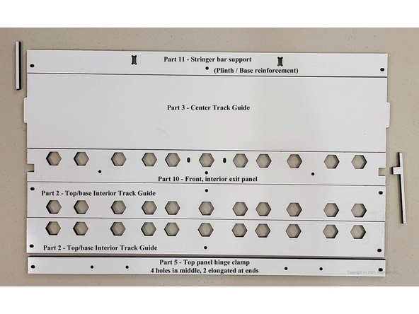
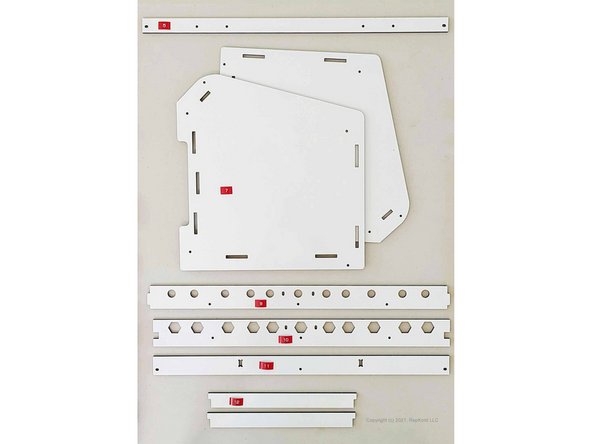
Another panel contains parts 11, 3, 10, 5, and two of panel part 2.
-
Part 11 is the Stringer Bar Support. It's easy to identify, being long and skinny with two dogbone-type holes in the middle.
-
Part 3 is the Center Track Guide. What happens with the RepBox is that this part and the Part 2 pieces on this sheet stand taller than the base panel (part 4), thus providing a channel or track for the rollers to rest in. This part is long and fairly wide with tabs on the ends.
-
Part 10 is the Front, Interior Exit Panel. It is the inside portion of the exit holes that lead out of the lower front "lip" of the box. This part is long and medium width. It has 11 hexagonal holes, 2 oblongs, 3 rounds, and most notably two squarish notches at the ends. Those notches are what distinguish Part 10 from Part 2.
-
The two Part 2 pieces are the "Outer" Track Guides. Like Part 3, they rest flat atop the base part 4 inside the box, one butting up against the front, and one against the back of the box. Each has 11 hexagonal holes, 2 elongated holes at the ends, and one circular hole at the middle.
-
Part 5 is the Top Panel Hinge Clamp. It is long and skinny, has 2 elongated holes at the ends, and 2 pairs of circular holes in the middle.
-
A conceptual note here: the hexagonal holes in parts 10 and 2 are designed to capture the plastic nuts that hold the Exit Fittings in place. As such, they lay flat inside the box against exterior parts 4 and 9. Only one of the part 2 pieces really is used for exit holes. You'll see why later during assembly.
-
-
-
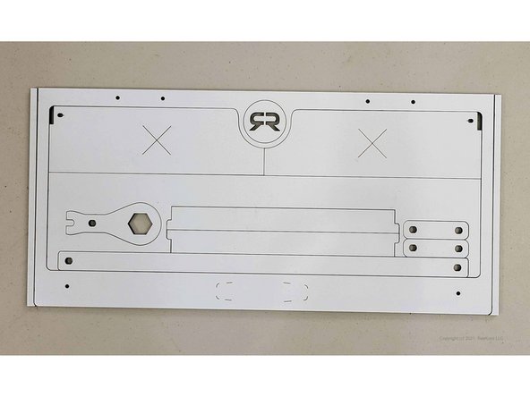
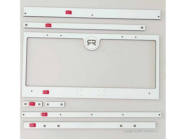
The last MDF panel contains parts 14, 15, a "drumstick tool", and two each of parts 12 and 17.
-
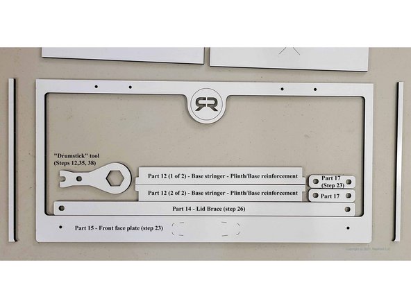
There two parts marked 'X' are not used. The piece directly surrounding the drumstick tool and other parts is also not used, but the one outside of that, Part 15, is the Front Face Plate, and that part is used. The second image shows more clearly what to keep.
-
Part 15 is the Front Face Plate. It is shaped like a license plate frame, and has the R logo and indicators for where the logo/label will be affixed.
-
Part 12 is the Base Stringer. It is middle-ish length, and has non-centered tabs at the ends. Those tabs eventually fit into the dogbone holes seen in Parts 1 (Rear Panel) and 11 (Stringer Bar Support), and all those go below the base panel 4.
-
Part 17 is a small, rounded rectangle. Each of these is used when mounting the faceplate to the hinges.
-
Part 14 is the Lid Brace. It is long, but not as long as most others, and skinny, and has two larger oblong holes at its ends.
-
-
-
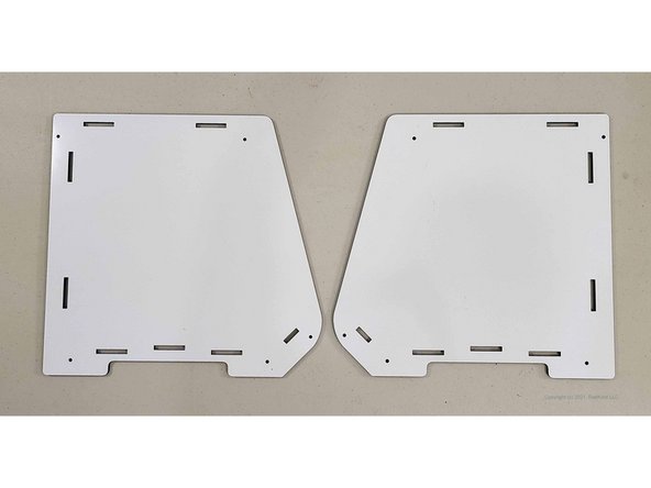
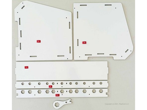
There are two part 7 pieces. One serves as the left side, and the other as the right side of the box. These are obvious in shape.
-
For this demo build, we're putting white on the outside. As such, the Part 7 on the left side of this picture is the left side of our built box.
-
-
-
The acrylic lid has the same dimensions as the Front Face Plate part 15. Since it is clear, it is not pictured here.
-
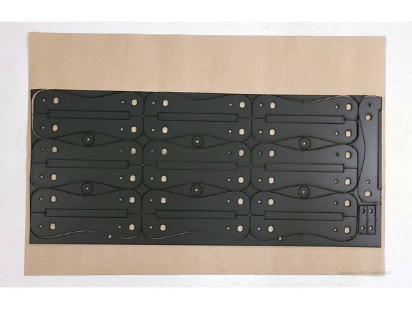
The styrene part sheet holds 6 styrene washers, 19 roller legs, and two part 30 pieces. The part 30 pieces are old-style, lower front braces, both actually supplanted now by a more rigid, 3D-printed part.
-
The second picture here shows the styrene panel partly disassembled. The small rectangles formed between pairs of roller legs are not used in the build.
-
-
-
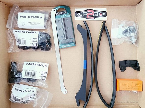
Shown here are various parts from the hardware tubes.
-
Parts Pack A contains the roller bearings that are used during the roller assembly step. Those are built after the main box is completed.
-
Note: the roller bearings may have excess grease, so it might be a good idea to lay them down on cardboard and/or a paper towel after unboxing them.
-
Parts Pack C contains Exit Plugs. Those are used to plug up holes in the top or base panel 4 in locations where you aren't using a Part D Exit Fitting.
-
Parts Pack D contains Exit Fittings. These are the parts that filament will go through as it exits the box.
-
Parts Pack E contains the screws used during the build of both the main box and the roller assemblies. All the screws are the same. They are also referred to as TF Screws in other build steps.
-
Other parts shown here include the lid lift bar, hinges, domed sticker, insulation strips, latch assembly, and the new 3d-printed front brace (that supplants styrene part 30). Depending on your order, you may get a subset of these parts.
-
-
-
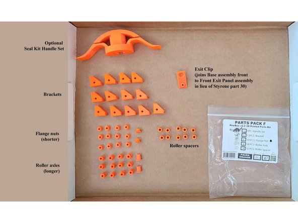
If you ordered the 3D-printed part set, you will receive parts like these. If not, you will need to print them.
-
The triangular pieces are brackets. Note the hole locations on these.
-
The Flange Nuts are the ones that are oblong and have a flat on one end. They are shorter than the similarly shaped Roller axles.
-
The Roller Axles are just like the Flange Nuts, but longer.
-
The cylindrical pieces are Roller Spacers.
-
Finally, the lid handle and the exit clip are shown.
-
-
-
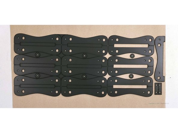
The panel parts are shown here in order of part number. The part number order is not related to the build order, so the next step will show them laid out in build order (roughly).
-
Also, the panel part numbers are not sequential. For example, you do not see part numbers 6 or 8 among the panel parts.
-
-
-
The pictures here show the panel parts in the order that they're used, roughly, during the build process.
-
It may be helpful for you to lay them out similarly so it's easier to find the pieces you need as you go through the assembly steps.
-
The layout of other parts (styrene parts, acrylic lid, roller pieces) are not shown similarly, since it's easier to identify them.
-
Detailed views of other things, like the optional latch, will be shown during the assembly.
-
Now that you have all the parts separated and laid out, you're ready to start building. Don't forget that you have to remove the protective film from both sides of acrylic pieces prior to assembly.
-

Cancel: I did not complete this guide.
One other person completed this guide.